3 video cable connection, 1 serial line connection, 4 serial line terminations – Videotec NTC User Manual
Page 11: 5 installing the housing, 1 fixing with bracket
Instruc
tions manual - English - EN
9
6.1.3 Video cable connection
The installation is type CDS (Cable
Distribution System), do not connect it to
SELV circuits.
Connect the video cable (RG-59) fitted with a BNC
connector to the board.
Fig. 6
6.1.3.1 Serial line connection
The installation is type TNV-1, do not
connect it to SELV circuits.
In order to reduce the risk of fire, only use
cable sizes greater than or equal to 26AWG.
The product has a RS-422 serial communication line.
J2
Fig. 7
Perform the connections following the instructions
reported in the table .
RS-422 LINE
Terminals
Description
SGND
GND RX signal
A1
RX+
B1
RX-
SGND
GND TX signal
A2
TX+
B2
TX-
Tab. 2
6.1.4 Serial line terminations
The board has two DIP switches used to configure the
serial line terminations (120 Ohm) (Fig. 4, page 8).
Every peripheral that is situated at the end of a line
must be terminated using the appropriate dip-switch
in order to prevent signal reflection and distortion.
Dip-switches 7 and 8 terminate serial lines RS485-1
and RS485-2 respectively.
DIP switches 1 and 2 terminate the RS422-RX and
RX422-TX serial lines, respectively.
RS-422 SERIAL LINE TERMINATIONS
DIP 1
DIP 2
Description
ON
-
RS422-RX, Line terminated
OFF
-
RS422-RX, Line not terminated
-
ON
RS422-TX, Line terminated
-
OFF
RS422-TX, Line not terminated
Tab. 3
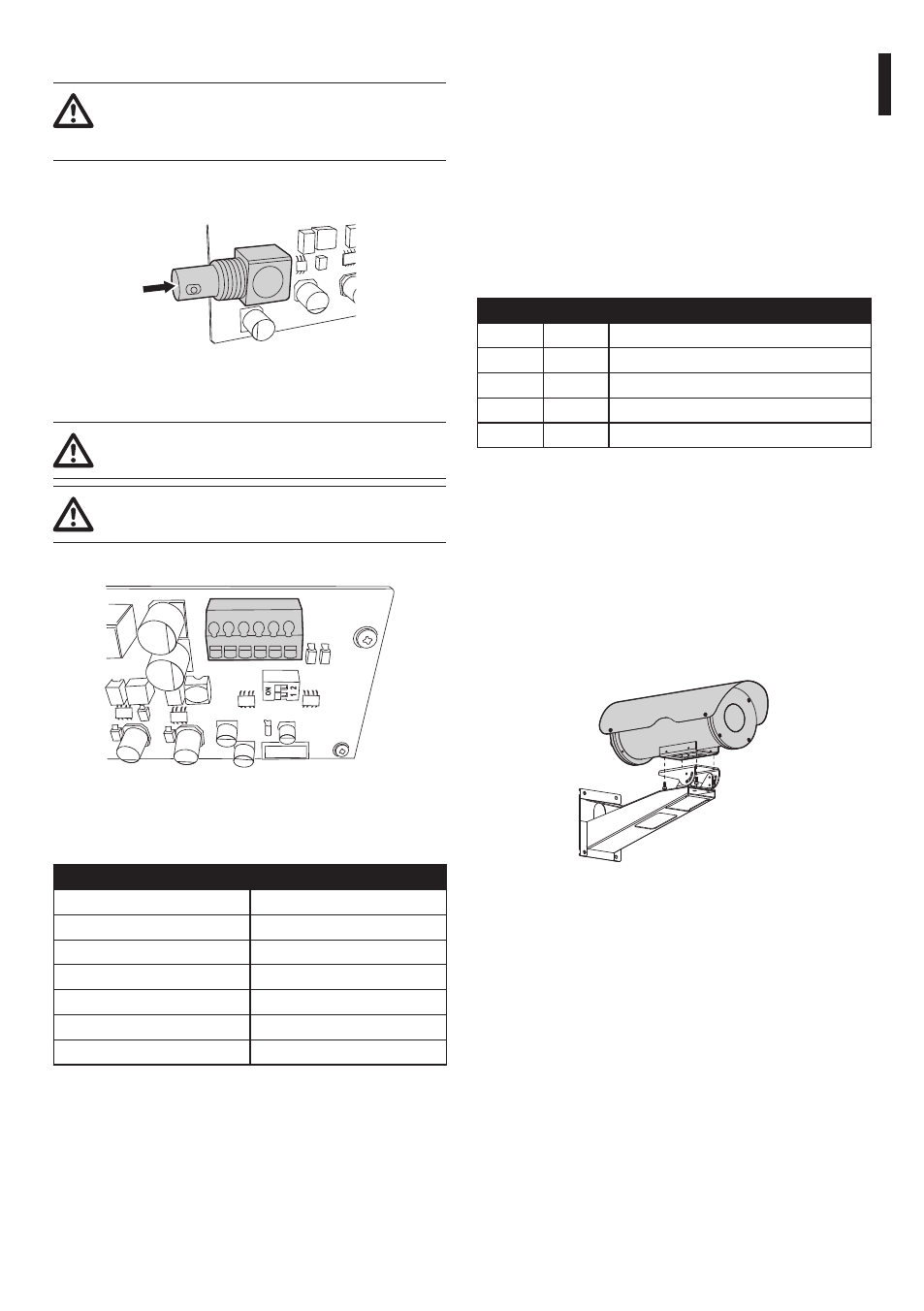
6.1.5 Installing the housing
Before closing the housing, be sure to have rightly
fitted the internal slide according to the type of
installation.
6.1.5.1 Fixing with bracket
The fixing base of the housing must be positioned
facing downwards.
Fig. 8