8 signal output of an ip camera, 9 connection of the ip camera's rs-485 output, 9 connection of the ip camera's rs- 485 output – Videotec MAXIMUS MHXT User Manual
Page 28
EN - English - I
nstruc
tions manual
28
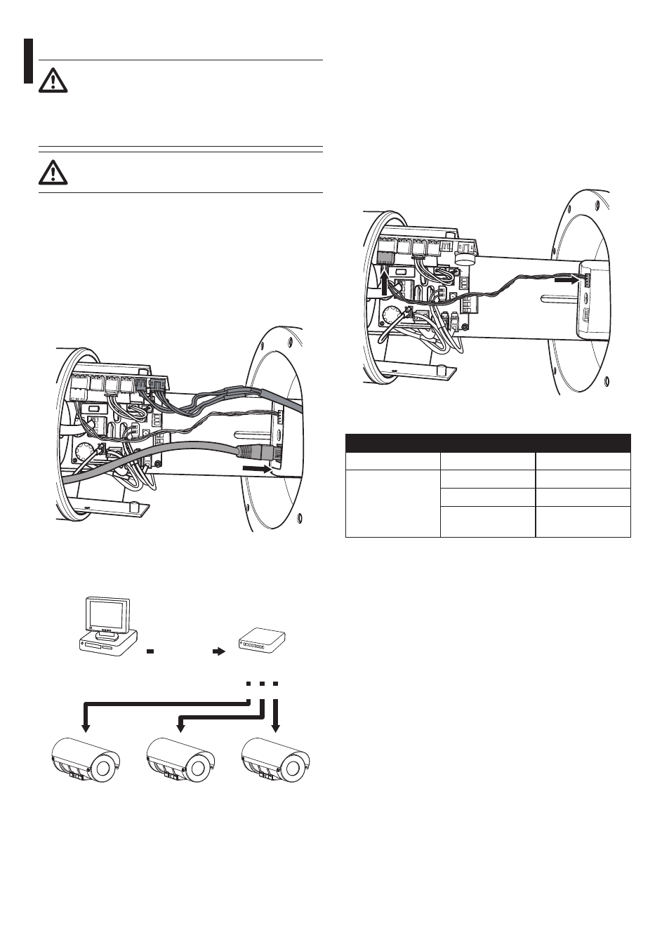
7.3.8 Signal output of an IP camera
Telemetry and video signal transmission
pass through the Ethernet network cable. If
the camera has a RS-485 output refer to the
relative chapter (7.3.9 Connection of the IP
camera's RS-485 output, page 28).
The installation is type TNV-1, do not
connect it to SELV circuits.
To connect the net cable a UTP: Category 5E or
superior, 4 pair, maximum length 100m (328ft).
Crimp the RJ45 connector on the Ethernet cable.
Crimping should be straight-through if passing via
a hub or switch while it should be crossover if you
are connecting directly to the PC for the necessary
checks.
Fig. 31
The example below shows a typical installation.
Hub / Switch
Personal
Computer
UTP cat 5E
UTP cat 5E
Fig. 32
7.3.9 Connection of the IP camera's RS-
485 output
If an IP camera with RS-485 output is used, working
with PELCO D (2400baud, 9600baud) or VIDEOTEC
MACRO (9600baud, 38400baud), this channel can be
used to send telemetry commands.
Connect the camera's RS-485 output to the CPU
board's J12 connector.
Fig. 33
CONNECTION OF THE RS-485 OUTPUT
Serial line
Terminal
Description
RS-485
A (+)
RS-485 line
B (-)
RS-485 line
AGND
Reference line
RS-485
Tab. 7