6 video signal output of an analogue camera, J6 j7 j13 – Videotec MAXIMUS MHXT User Manual
Page 26
EN - English - I
nstruc
tions manual
26
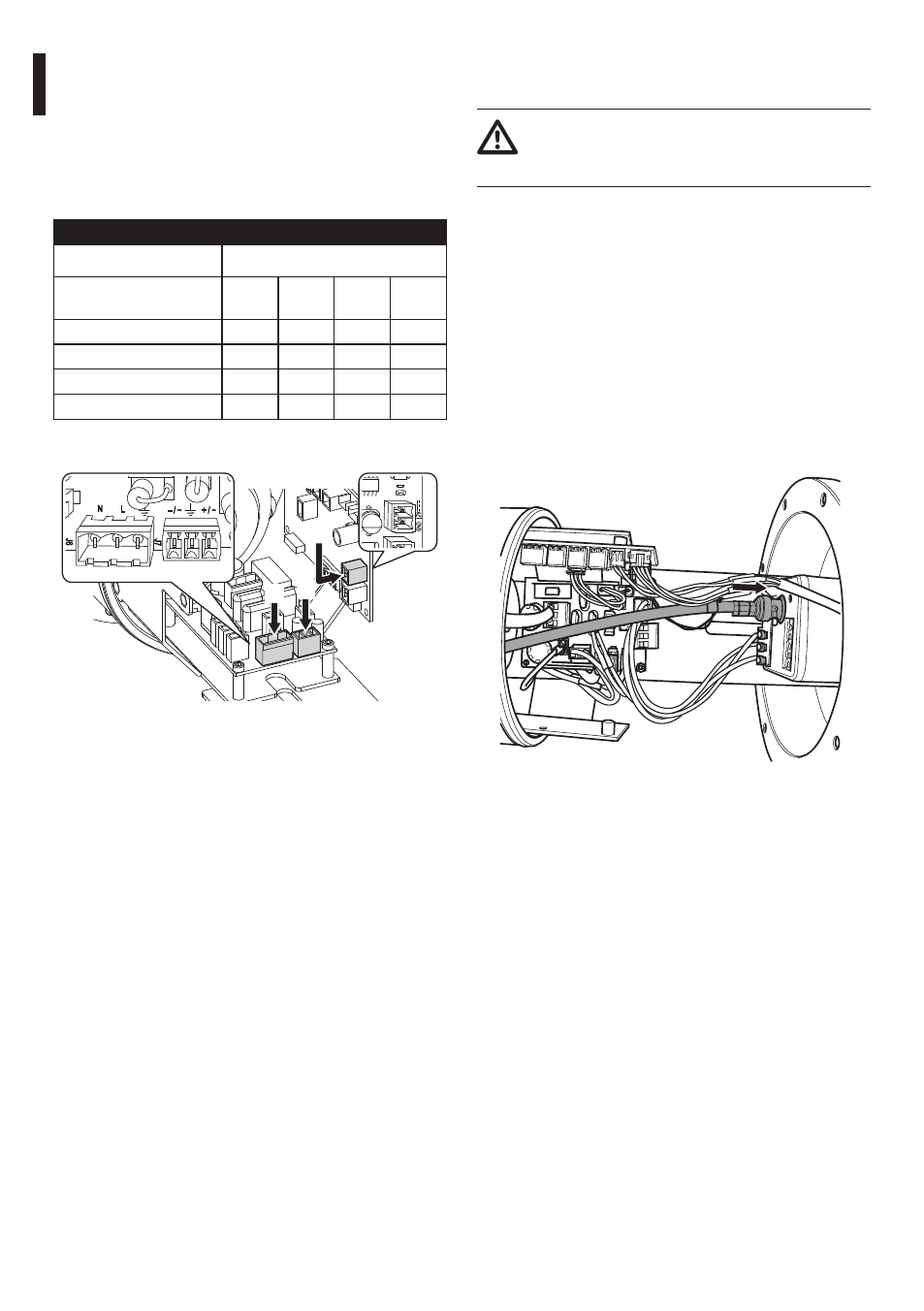
7.3.5.3 Connection of the camera's
power line in 12Vdc, 24Vac, 120Vac and
230Vac (with power supply)
Remove the removable connector from the board..
Carry out the wiring between the removable
connector and the camera's power supply terminals.
Re-insert the connector into the board.
CONNECTION OF THE CAMERA TO THE POWER SUPPLY
Input voltage of the housing
Input voltage of the
camera/lens
12Vdc 24Vac 230Vac 120Vac
230Vac
–
–
J6
–
120Vac
–
–
–
J6
24Vac
–
J7
J7
J7
12Vdc
J13
J13
J13
J13
Tab. 6
J6 J7
J13
TR OUT
J7
J6
N
– / ~
+ / ~
L
J13
J4
U3
X1
U5
U4
J14
U2
J1
J9
C1
L1
L10
ON
ON
OG
DIP 1
1 2 3 4 5 6 7 8
ALCO A D E 0 8
Fig. 27
7.3.6 Video signal output of an
analogue camera
The installation is type CDS (Cable
Distribution System), do not connect it to
SELV circuits.
If a camera is installed without the use of an analogue
fibre optic transmitter the video signal will be
released directly through the input/output device
cables.
Suggested coaxial cables are:
• RG59
• RG174A/U UL1354
Slide the coaxial cable along the input device.
Connect the coaxial cable to the camera's BNC video
connector. Use a 75Ohm BNC male connector (not
supplied).
Fig. 28