2 fastening of the wiper blade, 3 configuration, 1 configuration of the dip-switches – Videotec ULISSE MAXI NETCAM User Manual
Page 27: 2 dip1 configuration
Instruc
tions manual - English - EN
25
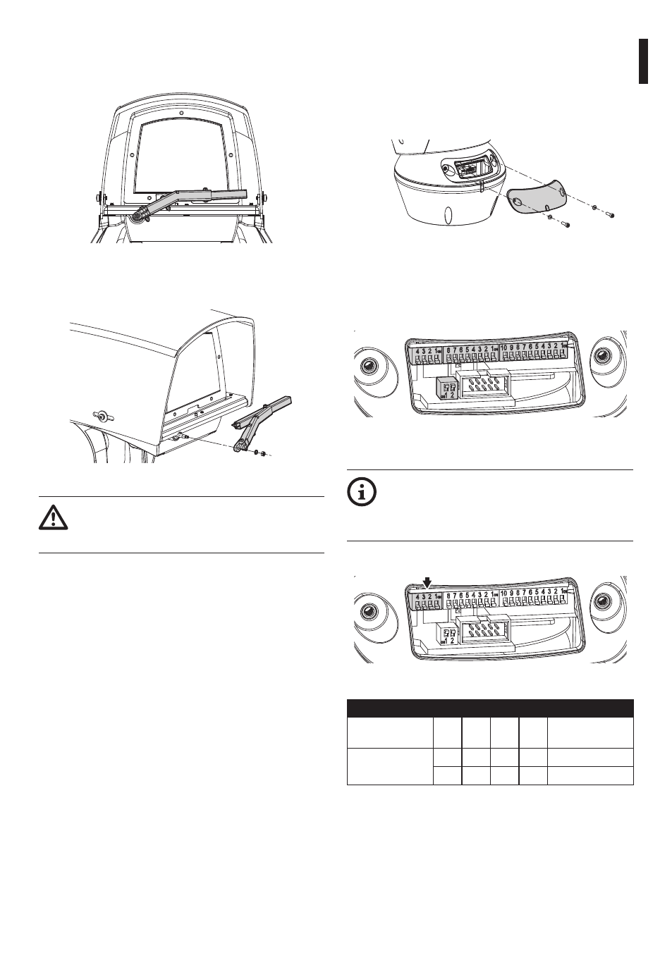
7.2.2 Fastening of the wiper blade
Insert the blade in the wiper shaft.
Fig. 45
Position the blade in the stop position.
Fig. 46
The correct adjustment must allow the
return of the blade to the stop position
going to the end stop on the casing’s plate.
Fasten the whole assembly by means of the washer
and nut.
7.3 Configuration
Before powering the device it must be configured
correctly by setting the dip-switches inside the
configuration hatch. Open the hatch by undoing the
screws as shown in the figure.
Fig. 47
7.3.1 Configuration of the dip-switches
Once the configuration cover is opened the dip-
switches will appear as shown in the figure.
Fig. 48
7.3.2 DIP1 configuration
When the dip-switch rocker is up it
represents the value 1 (ON). When the
dip-switch rocker is down it represents the
value 0 (OFF).
Dip-switch 1 is used to update the firmware.
Fig. 49
DIP1 CONFIGURATION
Description
SW
4
SW
3
SW
2
SW
1
Configuration
Firmware
updating
–
–
–
ON
Set up enabled
–
–
–
OFF Set up disabled
Tab. 7