4 connection of the ethernet cable – Videotec ULISSE MAXI NETCAM User Manual
Page 24
EN - English - I
nstruc
tions manual
22
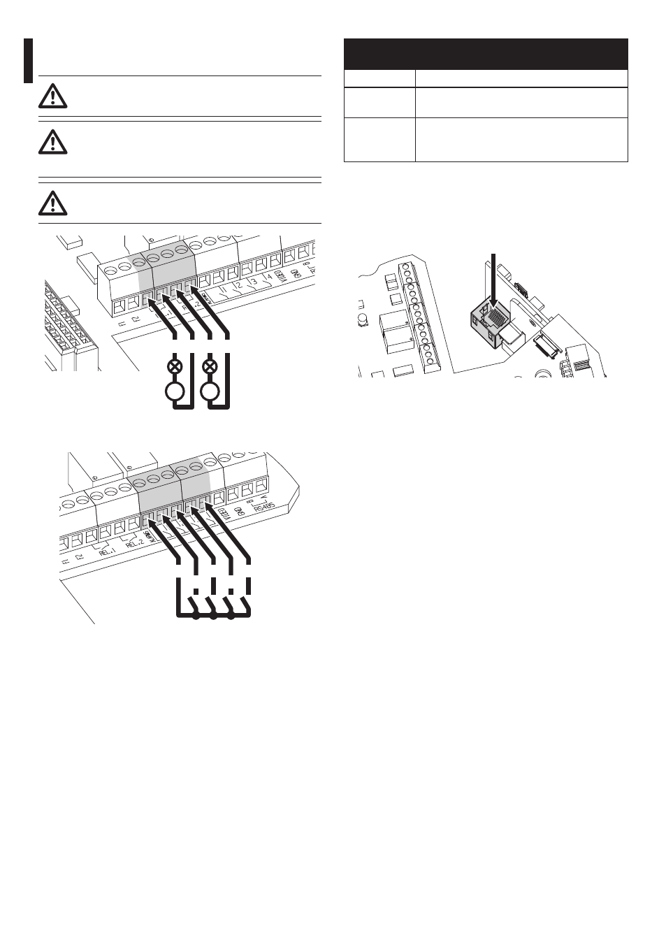
7.2.3.4 Connection of the alarm inputs, of
the twilight switch and of the relays
The installation is type TNV-1, do not
connect it to SELV circuits.
In order to reduce the risk of fire, only use
cable sizes greater than or equal to 26AWG
(0.13mm²).
All signal cables must be grouped together
by means of a strap.
O1 C1 O2 C2
V
V
Fig. 35
Relay contact connection.
AL4
AL3
AL2
AL1
AGND
Fig. 36
Alarm connection.
CONNECTION OF THE ALARM INPUTS, OF THE
TWILIGHT SWITCH AND OF THE RELAYS
Terminals
Description
O1-C1 and
O2-C2
Clean output contacts, can be activated by
alarm or by user control
AL1, AL2,
AL3, AL4 and
AGND
Self powered alarm inputs referring to AGND
Tab. 6
7.2.4 Connection of the ethernet cable
Connect the ethernet cable to the connector.
Ethernet
Fig. 37