46' to 62' hydraulic fold implement assembly, 46’ to 62’ set-up instructions -57 – 2-84 – Summers Hydraulic Fold Coil User Manual
Page 67
SECTION 2 - ASSEMBLY
2-57
SET-UP INSTRUCTIONS – 46’ to 62’ HYDRAULIC FOLD IMPLEMENT
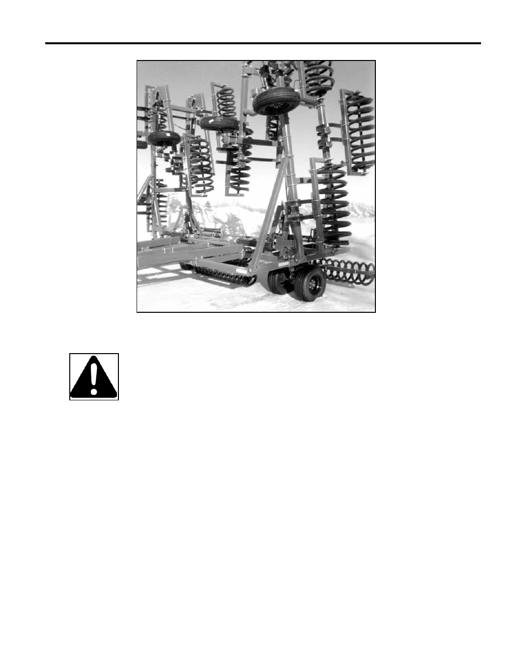
Refer to illustrations on following pages and follow these steps when assembling a 46’ to 62’ Sum-
mers Hydraulic Fold Coil Packer or Hydraulic Fold Rolling Chopper. The machine should be placed
in a firm, level area that allows ample room for assembly in field position.
CAUTION: For safety purposes, block equipment while working on it.
CENTER ASSEMBLY
Place Packer drawbar center section on stable supports approximately 2-1/2 ft. off floor. Install
cylinder attach Eye Bolts (8K1682C). Set Eye Bolts in middle of adjustment. Install hydraulic cyl-
inders. Secure Main Lift Cylinders with 1” diameter pins and cotter pins. Secure base end of Wing
Lift Cylinders (8C0432) with 1” diameter pins and roll pins. Install center wheel lift arm assemblies
with 1-1/4” X 14” pins. Apply good quality Anti-Seize lubricant on pins prior to assembly. Secure
with 1/2” X 1-3/4” cap screws, lock nuts and flat washers. Pre-Assemble Walking Axle assemblies.
Attach Walking Axle assemblies to lift arm assemblies with 3/4” bolts, lockwashers and nuts. Install
Wing Stops (8C5140) with ¾” u-bolts as shown in following drawings.
WING ASSEMBLY
Install left and right part 1 wings. Secure with 1-1/4” diameter pins and roll pins. Connect front and
rear wing sections with cross braces. Refer to coil layout drawing to determine brace locations.
Secure cross braces with 3/4” u-bolts. Attach part 2 wings to part 1 wings with 1” x 5-1/2” bolts. At-
tach part 2 wing lift cylinders and linkage as shown on page 7-5. Do not attach rod end of hydraulic
cylinders. Do not over tighten locknuts on lift linkages. Bolts must be free to rotate and slide freely
in lift slot. Attach wing axle assemblies using 3/4” u-bolts. Wing axle and hub assemblies are op-
tional on single coil/chopper wings.