AMETEK 1746 LDT Interface Card User Manual
Page 8
Chapter 1: Introduction & Overview
Installation & Programming Manual
4
Acknowledge Bit
This bit is set to indicate that the LDT input card recognized the 0 to 1 transition on the programming bit
and programmed the parameters requested. It is cleared when the programming bit goes back to zero.
Error Bit
This bit is set to indicate that the LDT input card recognized the 0 to 1 transition on the programming bit
but encountered an error when processing the data. It is cleared when the programming bit goes back to
zero.
Input State Bit(s)
These bits reflect the state of the inputs on the front of the 1746L LDT Interface Module. When the input
is active, the bit is a 1 and when the input is inactive, the bit is a 0.
Upper and Lower Limit Warning Bit(s)
These bits will indicate when an LDT has exceeded the upper or lower limit set for that specific LDT. For
the upper limit warning, the bit is set if the position of the LDT is greater than or equal to the upper limit
value. For the lower limit warning, the bit is set if the position is less than or equal to the lower limit
value. These bits are cleared when the position goes back into the operating range.
Movement Detection Bit(s)
There are 2 bits associated with each input. The first bit indicates when the input is active and there is
no movement detected on the LDT within a programmed amount of time. If this occurs, the bit is set. If
however, movement is detected, the bit is cleared. The second bit is for when the input is inactive and
there is movement detected on the LDT within a programmable amount of time. If this occurs, the bit is
set. If however, there is no movement detected when the input is inactive, the bit is cleared.
LDT Fault Bit(s)
This bit is set when an LDT is disconnected. It is cleared when there is no error. For cards with two LDT
circuits, there will be two separate error bits. These bits will automatically clear when the error condition
clears.
LDT Disconnected Bit(s)
This bit is set when no LDT connect is detected on the LDT circuitry. It is cleared when there is an LDT
connected. For 1746L LDT Interface Modules with two LDT channels, there are two separate error bits.
These bits will automatically clear when the error condition clears.
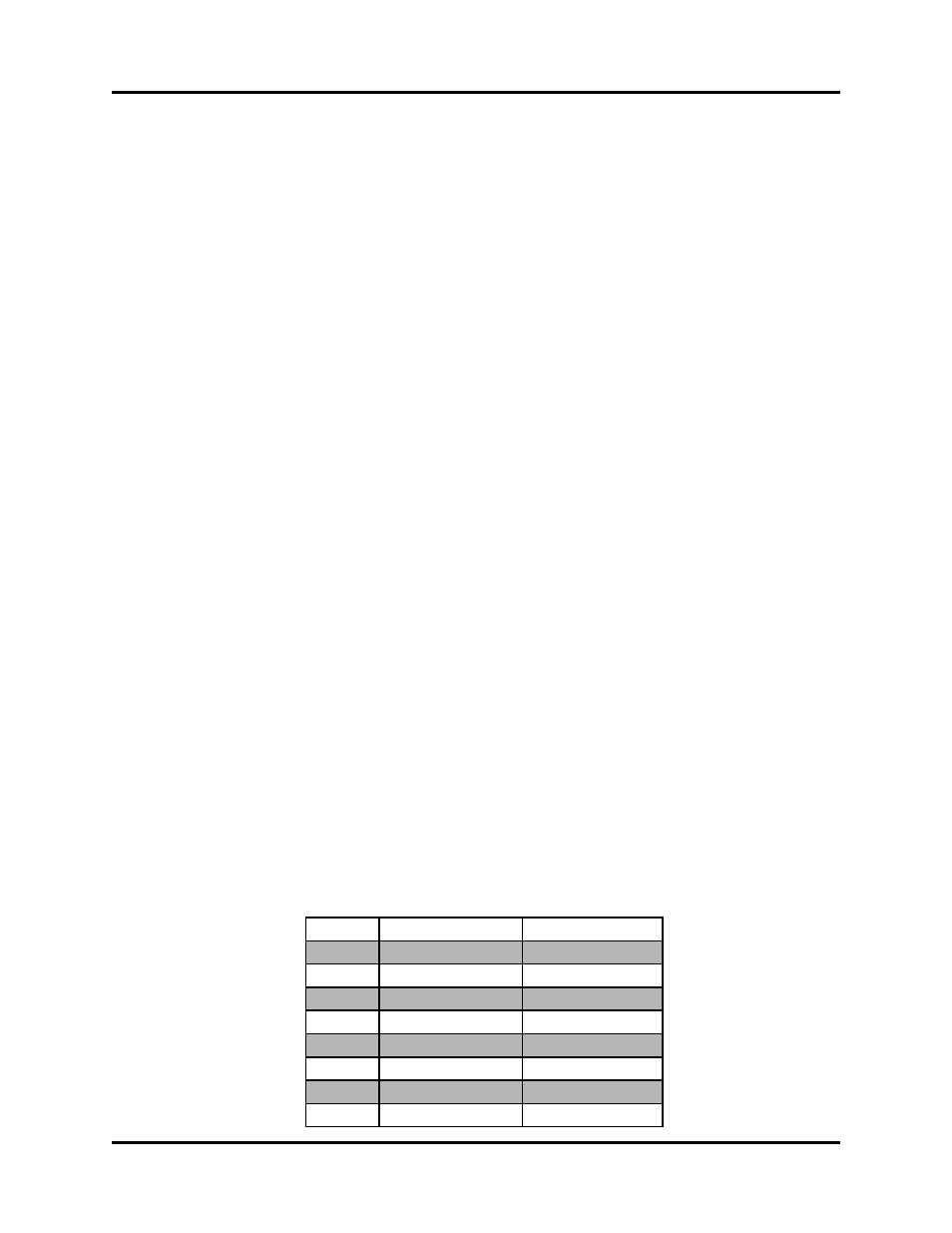
The following is how the Input Image Table would look for a single channel card and a dual channel card:
Single Channel
Dual Channel
Word 0 Status Bit Register
Status Bit Register
Word 1 Position 1 (high)
Position 1 (high)
Word 2 Position 1 (low)
Position 1 (low)
Word 3 Velocity 1
Velocity 1
Word 4
Position 2 (high)
Word 5
Position 2 (low)
Word 6
Velocity
Word 7