Status bit register – AMETEK 1746 LDT Interface Card User Manual
Page 17
13
Installation & Programming Manual
Chapter 3: Set-Up & Programming
Status Bit Register
The bit register has been defined below:
Acknowledge Bit
This bit is used to acknowledge a command from the output image table. If all the data is valid
in the command, the acknowledge bit is set to indicate to the SLC processor that the command
was processed. This bit is cleared when the programming bit is cleared in the output image table.
Data Error Bit
This bit is used to indicate an error was detected in the command sent from the output image
table. This bit is set if an error is detected in the command parameter data. This bit is cleared
when the programming bit is cleared in the output image table.
Input State 1
This bit will reflect the state of input 1 from the front of the unit.
Input State 2
This bit will reflect the state of input 2 from the front of the unit.
Upper Limit 1
This bit is set when the position exceeds the programmed upper limit for LDT 1. It is cleared
when the position is less than or equal to the programmed upper limit.
Lower Limit 1
This bit is set when the position falls below the programmed lower limit for LDT 1. It is cleared
when the position is greater than or equal to the programmed lower limit.
Upper Limit 2
This bit is set when the position exceeds the programmed upper limit for LDT 2. It is cleared
when the position is less than or equal to the programmed lower limit.
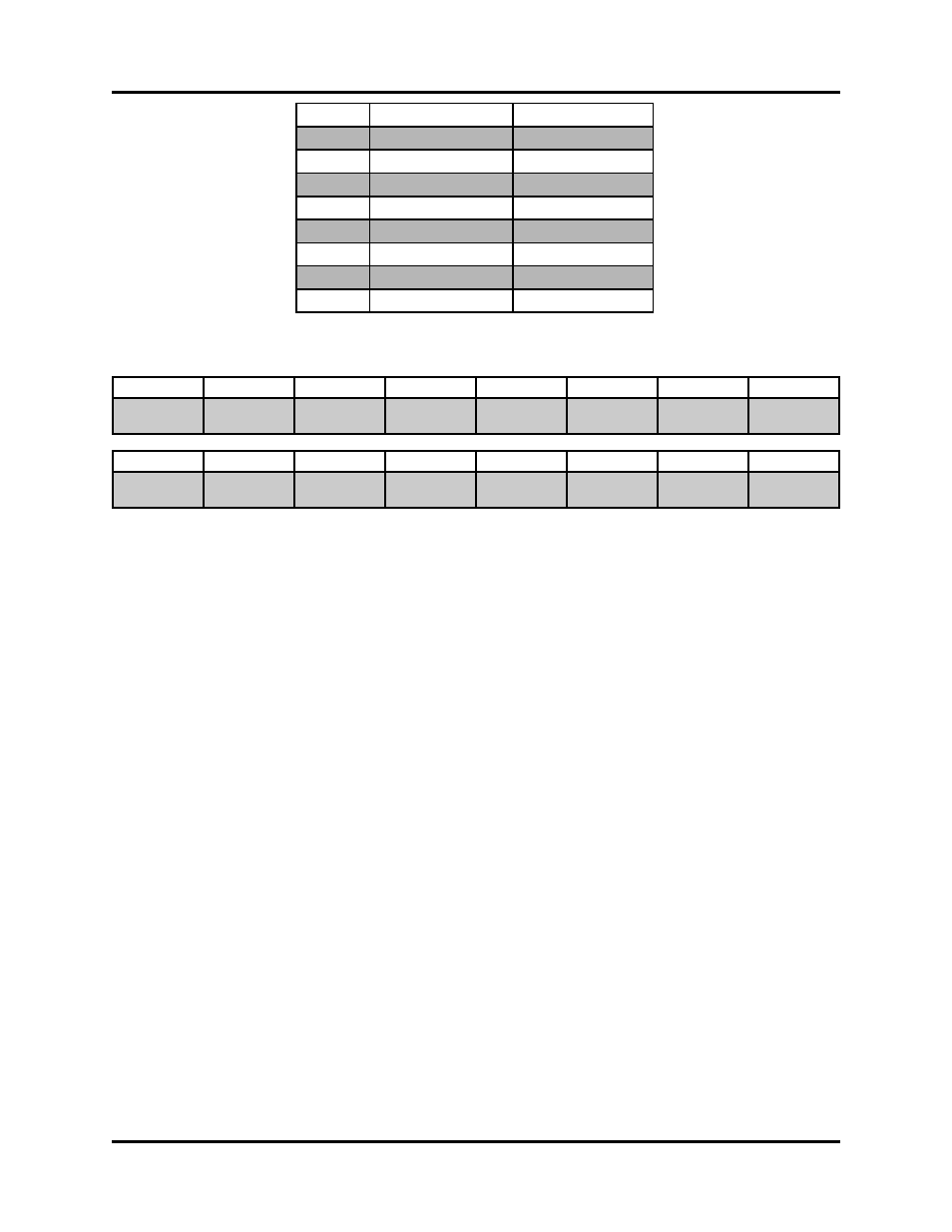
Single Channel
Dual Channel
Word 0 Status Bit Register
Status Bit Register
Word 1 Position 1 (high)
Position 1 (high)
Word 2 Position 1 (low)
Position 1 (low)
Word 3 Velocity 1
Velocity 1
Word 4
Position 2 (high)
Word 5
Position 2 (low)
Word 6
Velocity
Word 7
Bit 15
14
13
12
11
10
9
8
ACK
DATA ERR
INPUT
STATE 1
INPUT
STATE 2
UPPER
LIMIT 1
LOWER
LIMIT 1
UPPER
LIMIT 2
LOWER
LIMIT 2
Bit 7
6
5
4
3
2
1
0
MOVE
ERR 1
NO MOVE
ERR 1
MOVE
ERR 2
NO MOVE
ERR 2
LDT 1
FAULT
LDT 1
NO CONN
LDT 2
FAULT
LDT 2
NO CONN