Chapter 4.pdf, Chapter 4: application examples – AMETEK 1746 LDT Interface Card User Manual
Page 19
15
Installation & Programming Manual
Chapter 4: Application Examples
Chapter 4: Application Examples
The following is an example program for setting up the 1746L LDT Interface Module. The
1746L LDT Interface Module is installed in slot 1 of the SLC 500 rack.
The following data defines the command parameters and state flags that are used to program the
1746L LDT Interface Module:
Configuration Command
#N7:0
LDT Configuration Command for LDT 1 #N7:10
LDT Configuration Command for LDT 2 #N7:20
Program State Flags
#N9:0
1746L Configuration
#N9:0/0
LDT 1 Configuration
#N9:0/1
LDT 2 Configuration
#N9:0/2
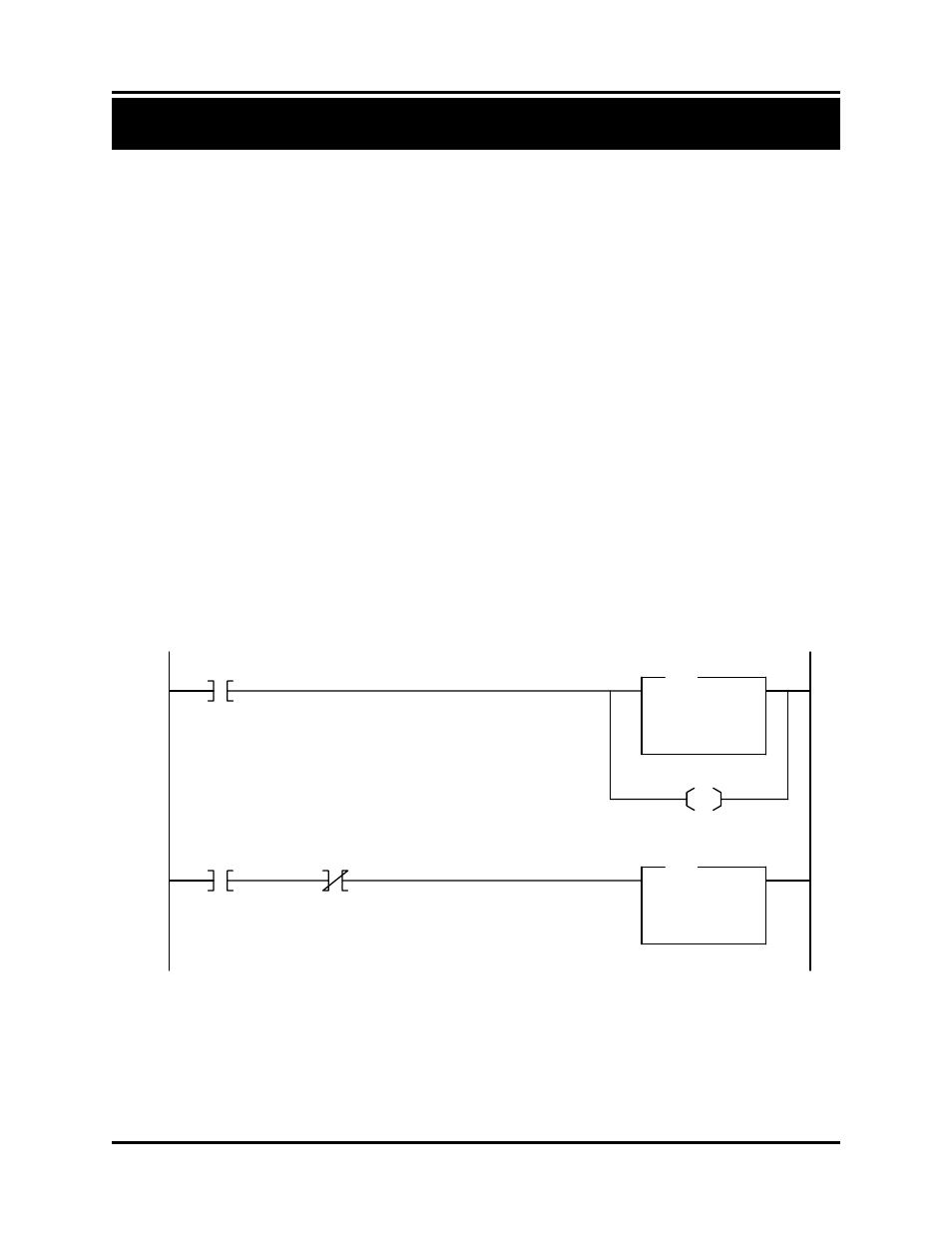
On the first scan, the start 1746L configuration flag is set. When this flag is set, the configuration
command is copied into the output image table with the programming bit set. The parameters
sent with this command tell the unit that LDT 1 and 2 are control pulse LDTs and the inputs are
configured for position hold. This will continue until the command has been acknowledged in
the input image table.
When the configuration command is complete, the program will copy the LDT configuration
command for LDT 1 into the output image table with the programming bit set. This command
will configure LDT 1 for the speed of wire, count direction, recirculations, and LDT length. The
speed of wire for LDT 1 is 9.300µs/inch. The counts are defined as increasing from the LDT
head. There is only 1 recirculation and the LDT length is 12.0 inches. This continues until the
command has been acknowledged.
Move
Source 1
1<
Dest N:9.0
0<
MOV
CLEAR STATE FLAGS AND SET UP FOR INITIALIZATION
0000
Copy File
Source #N7:0
Dest #O:1.0
Length 8
COP
0001
First Pass
S2:1
15
0
N9:0
Config Bit Set
COPY THE COMMAND TO CONFIGURE THE 1746L CARD
Ack Bit Cleared
I:1
15
OTHER
U
Clear Program Bit
O:1
15
OTHER