Chapter 3.pdf, Chapter 3: setup & programming, Getting started – AMETEK 1746 LDT Interface Card User Manual
Page 11: Output image table, Command bit register, Programming bit, The command bit register has been defined below
7
Installation & Programming Manual
Chapter 3: Set-Up & Programming
Getting Started
Before the 1746L PLC LDT Interface Module can communicate with the A-B SLC 500
processor, the system must be configured to include the 1746L PLC LDT Interface Module. This
is done through either the APS Software or the hand-held controller. When defining the system,
the program will prompt for a SPIOGA ID code. The ID code for the 1746L PLC LDT Interface
Module is: 3535. This tells the processor that the 1746L uses 8 input words and 8 output words.
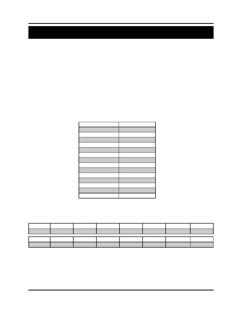
Output Image Table
Because there are more than 8 parameters to program, the 1746L Interface Module uses a
command based programming sequence to enter parameters into the system. The first word of
the output image table is the command bit register. This bit register contains a programming bit
used to initiate the programming sequence. The second word is the command word and the other
5 words are used for the command parameters as shown in the table below:
Command Bit Register
The Command Bit Register has been defined below:
Programming Bit
The software monitors the programming bit for a 0 to 1 transition. When this is detected, it reads
the command register and processes the data based on the command specified. If the command
data and parameter data are valid, the acknowledge bit is set in the input image table bit register.
If the data is invalid, the error bit will be set in the input image table bit register. These bits are
cleared when the programming bit is set back to zero.
Chapter 3: Setup & Programming
Output Image Table
Description
Word 0
Command Bit Register
Bits 15
Programming Bit
Bits 14 - 8
Reserved
Bits 7
Data Format Bit
Bits 6
Velocity Bit
Bits 5 - 1
Reserved
Bit 0
Inch/mm
Word 1
Command Register
Word 2
Parameter 1
Word 3
Parameter 2
Word 4
Parameter 3
Word 5
Parameter 4
Word 6
Parameter 5
Word 7
Parameter 6
Bit 15
14
13
12
11
10
9
8
PROG
RSVD
RSVD
RSVD
RSVD
RSVD
RSVD
RSVD
Bit 7
6
5
4
3
2
1
0
Data Format
Velocity
RSVD
RSVD
RSVD
RSVD
Filter Enable Bit
INCH/MM