HighPoint RocketRAID 2210 User Manual
Page 13
RocketRAID 2210 Hardware Description/Installation
2 - LED Connections
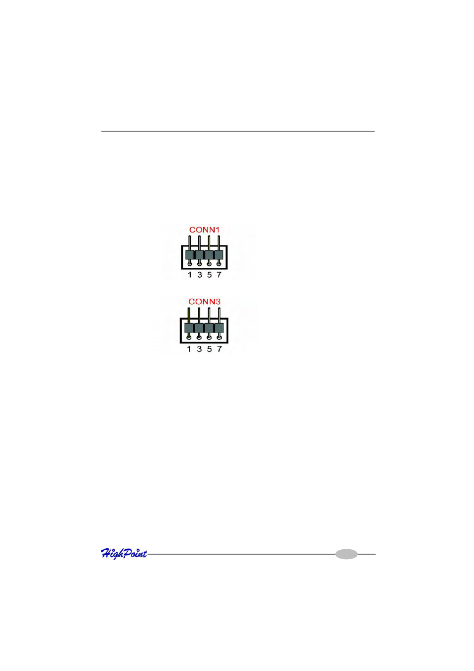
The RocketRAID 2210 has two LED jumpers that are used to indicate the activity and
failure status of hard disks attached to the card’s four SATAII channels. These jumpers
are labeled as CONN# (connector).
The odd numbered pins of each CONN (1, 3, 5, and 7) represent the RocketRAID
2210’s SATA channels 1, 2, 3, and 4 respectively.
CONN3 - Hard Disk Failure LED’s.
3 - Installing the RocketRAID 2210 Host Adapter
Note: Make sure the system is powered-off before installing the RocketRAID 2210
host adapter.
The RocketRAID 2210 includes both standard and low-profile brackets. It may be
necessary to attach the low-profile bracket in place of the standard bracket, depend-
ing upon the chassis design.
1.
Open the system chassis and locate an unused PCI-X slot.
2.
Remove the PCI slot cover.
3.
Gently insert the RocketRAID 2210 into the PCI slot, and secure the bracket to
the system chassis.
CONN1 - Hard disk Activity LED’s.
2-2
- RocketStor 6328 (40 pages)
- NA762TB (12 pages)
- NA762TB (41 pages)
- NA381TB (3 pages)
- NA333TB (3 pages)
- NA211TB-LD (3 pages)
- RocketRAID 4520 (8 pages)
- RocketRAID 2720C2 (19 pages)
- Rocket 2722 (8 pages)
- RocketRAID 2782 (60 pages)
- RocketRAID 2760 (60 pages)
- RocketRAID 2744 (65 pages)
- RocketRAID 2722 (23 pages)
- RocketRAID 4322 (60 pages)
- RocketRAID 4460 (59 pages)
- RocketRAID 2684 (35 pages)
- RocketRAID 2644X4 (84 pages)
- RocketRAID 2642 (35 pages)
- RocketRAID 362x (8 pages)
- RocketRAID 640L (8 pages)
- Rocket 640L (8 pages)
- RocketRAID 622 (8 pages)
- RocketHybrid 1220 (43 pages)
- RocketRAID 3560 (62 pages)
- RocketRAID 3520 (80 pages)
- RocketRAID 2522 (90 pages)
- RocketRAID 2340 (76 pages)
- RocketRAID 2322 (73 pages)
- RocketRAID 2320 (77 pages)
- RocketRAID 2314 (92 pages)
- RocketRAID 2310 (75 pages)
- RocketRAID 2302 (81 pages)
- RocketRAID 2300 (81 pages)
- RocketRAID 2240 (72 pages)
- RocketRAID 2224 (54 pages)
- RocketRAID 2220 (46 pages)
- RocketRAID 1742 (65 pages)
- RocketRAID 1720 (71 pages)
- Rocket 622 (8 pages)
- RocketRAID 644 (7 pages)
- RocketStor 5422A (2 pages)
- RocketStor 5411A (2 pages)
- RocketStor 5422 (8 pages)
- RocketStor 5122B (29 pages)