Wiring, Standard wiring, Figure 7 – Vaisala DPT145 User Manual
Page 28: Wiring non-isolated rs-485
User's Guide _______________________________________________________________________
28 ___________________________________________________________________ M211371EN-D
Wiring
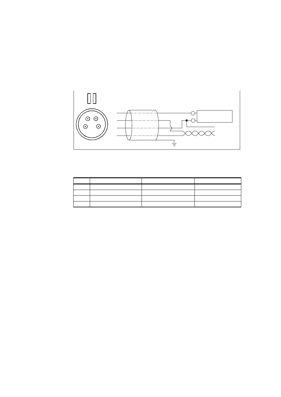
Standard Wiring
Connect supply voltage and RS-485 to port II. Port I does not need to be
used at all, and can remain covered.
1108-015
Figure 8
Wiring Non-Isolated RS-485
Wire Colors for Vaisala Cables
Pin
Connection on Port I Connection on Port II Wire Color
1
VDC supply+
VDC supply+
Brown
2
RS-485 D0-
White
3
GND
GND
Blue
4
RS-485 D1+
Black
Note the following:
- The ground pin (pin 3) on both ports is internally connected to each
other and to transmitter chassis. The chassis connection is through a
1 MΩ resistor and a 40 nF capacitor that are connected in parallel.
- The frames of the M8 connectors are not connected to the chassis.
15 ... 28 VDC
RS-485 +
RS-485 -
GND
+
SHIELD
-
1
2
3
4
2
4
1
3