Dip switch functions, Figure 23 – Vaisala HMT360 User Manual
Page 47
Chapter 4 ________________________________________________________________ Operation
VAISALA_______________________________________________________________________ 45
DIP Switch Functions
The table below is also printed on the protection board:
0505-285
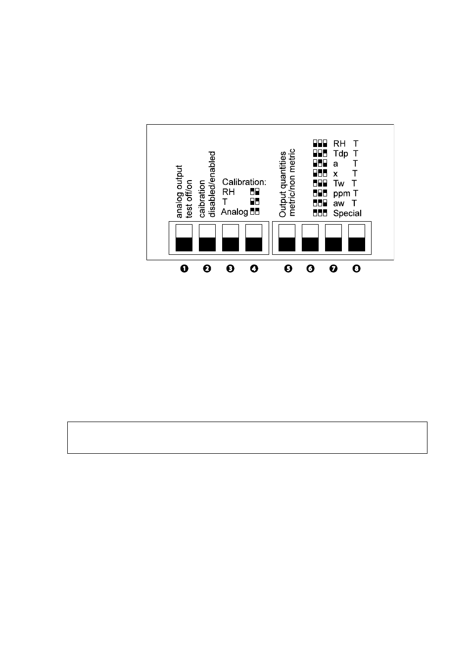
Figure 23
DIP Switch Functions
1: Analog output test on/off
If you turn the switch to on position (up), you can force the outputs to states
4 mA, 12 mA and 20 mA by pressing buttons Up and Dn on the cover.
Outputs return to normal mode when switch is turned down.
2: Calibration Disabled/Enabled
The EEPROMs are write protected. If this switch is in the disabled position
(down), it does not allow any calibrations or scalings.
3 and 4: Calibration rh, t, analog
With these combinations you can perform relative humidity, temperature
or analog output calibrations with a multimeter or with the transmitter
display unit. Turn the DIP switches to the desired position according to the
table printed on the protective cover.
5: Output quantities
Determines whether the output units are metric (down) on non-metric.
NOTE
Keep this switch always in the disabled position during normal use of the
transmitter.