Figure 16 – Vaisala HMT360 User Manual
Page 35
Chapter 3 _______________________________________________________________ Installation
VAISALA_______________________________________________________________________ 33
0505-277
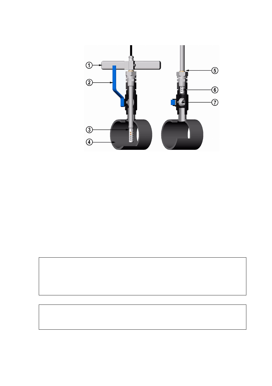
Figure 16
Installing the HMP368 Probe Through a Ball Valve
Assembly
The numbers below refer to
:
1
=
Manual press tool
2
=
Handle of the ball valve
3
=
Probe
4
=
Process chamber/pipeline
5
=
Groove on the probe indicating the upper adjustment limit
6
=
Filter
7
=
Ball of the ball valve
NOTE
The probe can be installed in the process through the ball valve assembly
provided that the process pressure is less than 10 bar. This way, the
process does not have to be shut down when installing or removing the
probe. However, if the process is shut down before removing the probe,
the process pressure can be max. 20 bar.
NOTE
When measuring temperature dependent quantities make sure that the
temperature at the measurement point is equal to that of the process,
otherwise the moisture reading may be incorrect.