Probe mounting, Figure 7, Parts of the transmitter – Vaisala HMT360 User Manual
Page 26
User’s Guide ______________________________________________________________________
24 ___________________________________________________________________ M010056EN-J
0603-038
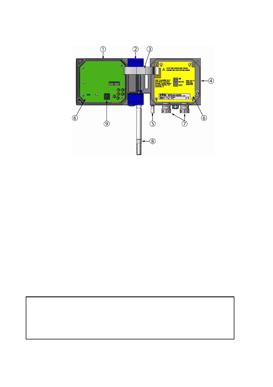
Figure 7
Parts of the Transmitter
Probe Mounting
The following numbers refer to
1
=
Electronics unit
2
=
Probe; including a part of the measurement electronics (for
example, calibration memory)
3
=
Flat cable
4
=
Transmitter base
5
=
Grounding terminal
6
=
Protective covers
7
=
Cable glands
8
=
Probe
9
=
RS232C connector
CAUTION
Do not unsolder and then resolder the probe cable from and to the printed
board during installation.
Do not shorten or lengthen the probe cable.
These procedures may alter the humidity calibration of the transmitter.
See also other documents in the category Vaisala Humidifiers:
- Calibration of Digital Transmitters with HMI41 (36 pages)
- Calibration of Series HMDW2030 and HMP130 Transmitter with HMI41 (14 pages)
- Calibration of Series HMDW6070 and HMP140 Transmitter with HMI41 (30 pages)
- HM34 (30 pages)
- HM40 (47 pages)
- HM44 (52 pages)
- HM70 (83 pages)
- HMD40 (1 page)
- HMD60 (4 pages)
- HMD70 (18 pages)
- HMDW110 (62 pages)
- HMDW80 (51 pages)
- HMI41 (74 pages)
- HMP41 (72 pages)
- HMK15 (39 pages)
- HMM100 (71 pages)
- HMM105 (23 pages)
- HMM211 (42 pages)
- HMM212 (36 pages)
- HMM213 (52 pages)
- HMP140 (28 pages)
- HMP155 (84 pages)
- HMP228 (115 pages)
- HMP230 (163 pages)
- HMP240 (130 pages)
- HMP260 (118 pages)
- HMP60 (71 pages)
- HMT100 (52 pages)
- HMT120 (87 pages)
- HMT130 (95 pages)
- HMT140 (76 pages)
- HMT310 (88 pages)
- HMT310 (105 pages)
- HMT330 (209 pages)
- HMT360 (63 pages)
- HMT360N (110 pages)
- HMW40 (1 page)
- HMW90 (110 pages)
- SHM40 (68 pages)
- RDP100 (14 pages)