Vaisala HMP240 User Manual
Page 62
HMP240
User's Guide
M210300en
60
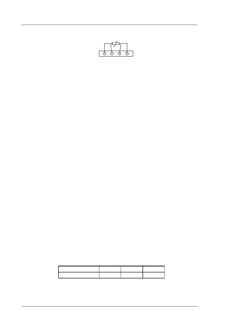
X88
Pt 100
Figure 7.4
Connecting the Pt 100 simulator to connector X88
Switch the power on.
7.5.1.1
With serial commands
Give command CT, enter the first point value and press
>CT
C : xx.x Ref1 ? yy.y
Press any key when ready
Set the Pt 100 simulator at the highest temperature to be calibrated and press
any key. Enter the second point (gain) reference reading.
7.5.1.2
With display commands
Select Cali in the main menu and then T; select two-point calibration T 2 point
cal. Change the first point reading with arrow keys and press ENT.
Set the Pt 100 simulator at the highest temperature to be calibrated and adjust
the second point (gain) to the reference reading.
7.5.2
With LED commands
Connect an ammeter/voltmeter to the analogue outputs (connector X2). Give
command ¡¡l¡ and adjust the first point (offset) with arrow switches to the
same reading with the reference and press ENT switch.
Set the Pt 100 simulator at the highest temperature to be calibrated and adjust
the second point (gain) to the reference reading.
Disconnect the Pt 100 simulator and reconnect the Pt 100 wires to solder lugs
TP5, TP6 and TP7.
The correct connections according to wire colours are:
TP5
TP6
TP7
HMP240
blue
green
yellow
7.6
Measurement of output currents using test points
If a current output has been connected e.g. to a process computer, the output
current cannot be measured at the output connector X2 without disconnecting