Appendix 6: hmp240 wiring diagram, Appendix 6: hmp243 wiring diagram, Hmp243 wiring diagram – Vaisala HMP240 User Manual
Page 120: Main board hmp240cb
HMP240
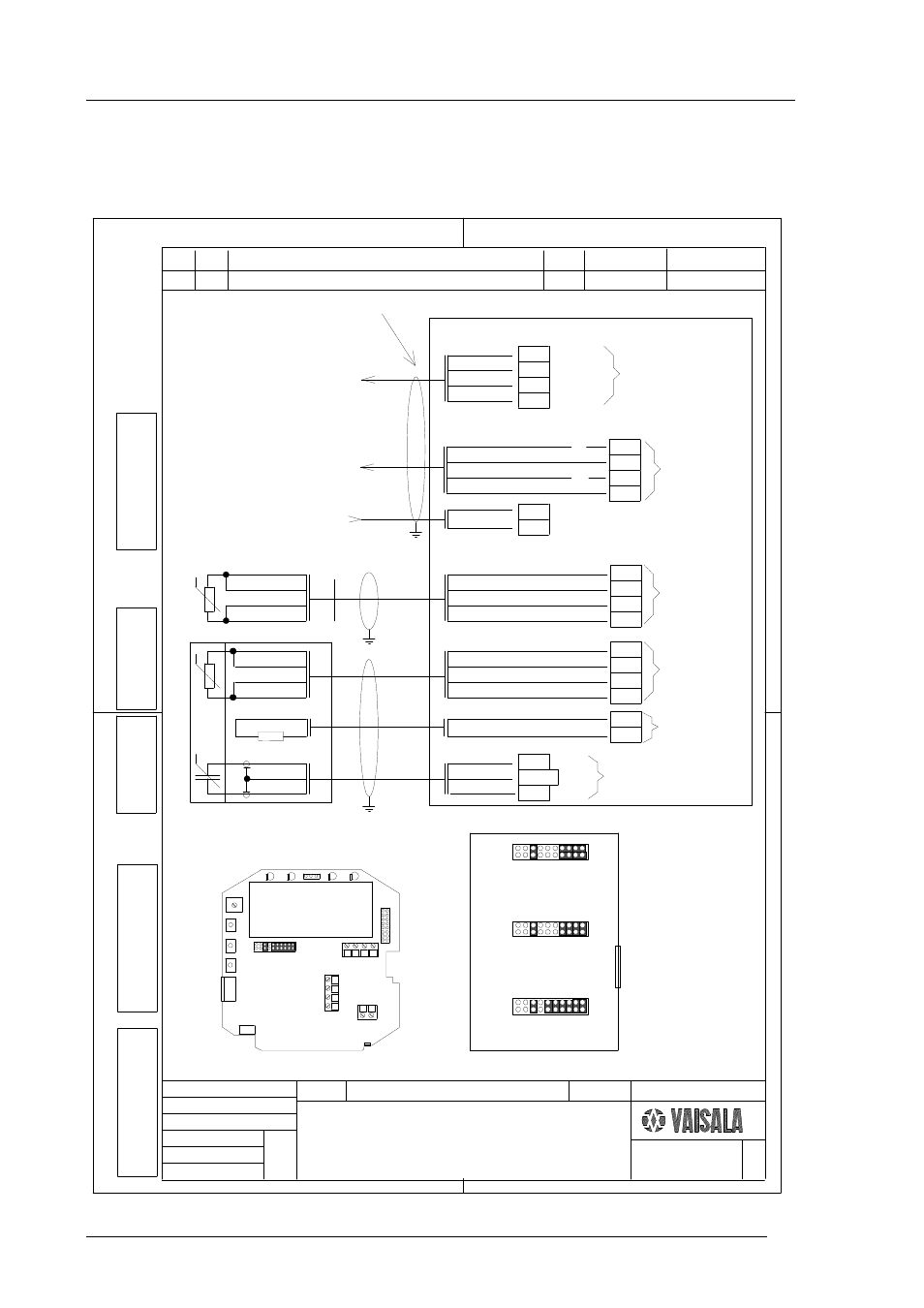
Appendix 6: HMP243 wiring diagram
M210300en
118
APPENDIX 6: HMP240 WIRING DIAGRAM
Jumper selections in connector X15
Current 0...20 mA/4...20 mA
Ch1
Ch2
Ch1
Ch2
Ch1
Ch2 Ch1
Ch2
Ch1
Ch2
Ch1
Ch2
Voltage 0...1 V
See manual for details!
Voltage 0...5 V/0...10 V
HMP243
Wiring diagram
In automation system
the galvanically isolated inputs
are recommended for current signals
Main board HMP240CB
To Control system
Supply voltage 24 VDC
Note ! The cable shield has to be connected to the cable bushing for full EMC protection.
(To Control system)
X2
1
2
3
4
1
2
3
1
2
4
Channel1+
Channel1-
Channel2+
Channel2-
RX
GND
TX
NC
-
+
Serial
connections
See manual for
details!
Humidity and
temperature outputs
current/voltage
Max load for
mA outputs 500 ohm
max 270 mA (24VDC)
X6
X1
Probe connections
X2
1 2 3 4
4
3
2
1
2 1
X1
X6
Location of main board terminals
X15
Replaced
by
Drawn
Review
Appr
Design
Replaces
Scale
id
Title
Arch
no
Serial
Sheet
doc no
Cooperator`s
Dwg no
Rev
Ltr
Qty
Change
Reason/
ECO no
Design
Date Review
Date Appr
Work order
Tool
Qty
pcs
+RX
-RX
+TX
-TX
TX
RX
RS232
Digital cur-
rent loop
RS485
HI
LO
LO
HI
95-08-24 KKe
MK45003
A
BLU
BLK
YEL
GRN
TP5
TP6
TP7
TP8
Probe cable length 2, 5 or 10 m
Sensor
temperature
4 wire connection
Pt 100
TP12
TP11/15
TP13
RH sensor
Humicap
GND
RH2
RH1
Process temperature/Option
WHT
BLK
RED
BLU
TP1
TP2
TP3
TP4
Process
temperature
4 wire connection
Pt 100
TP24
TP25
Heating resistor
WHT
RED
Composite sensor
95-08-24 KKe
NOTE
The output settings must
also be programmed
Appendix 6: HMP243 wiring diagram
(for 24 VAC, see
the Operating Manual)