Vaisala HMP240 User Manual
Page 61
HMP240 series
M210300en
User's Guide
59
Disconnect the Pt 100 simulator and reconnect the Pt 100 wires to solder lugs
TP1, TP2 and TP3.
The correct connections according to wire colours are:
TP1
TP2
TP3
blue
white
red
If a Pt 100 simulator is not available, the adjustment can be made with two
resistors of 84
Ω
and 154
Ω
with precisely known resistance. Measure
resistors with a resistance meter. Look up the corresponding temperature value
from a Pt 100 conversion table or calculate it according to the following
equation:
T = D0 +R x {D1 + R x [D2 + R x (D3 + R x D4)]}
where
D0
=
-243.5673014
D1
=
2.278542701
D2
=
0.002050681
D3
=
-6.15025E-06
D4
=
1.34949E-08
7.5
Temperature channel adjustment with Pt 100 simulators
(composite sensor)
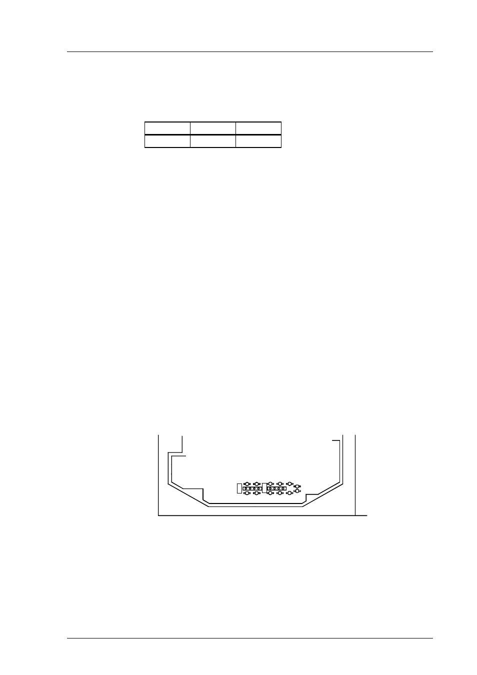
Switch the power off and disconnect the wires to the Pt 100 sensor from solder
lugs TP5, TP6 and TP7.
X
7
7
X
8
8
TP6 TP7
TP5
Figure 7.3
Location of solder lugs TP5, TP6 and TP7 and connector
X88
Connect a Pt 100 simulator to connector X88 and set it at the lowest tempera-
ture to be calibrated.