Vaisala HMP240 User Manual
Page 11
HMP240 series
M210300en
User's Guide
9
3.2
Mounting
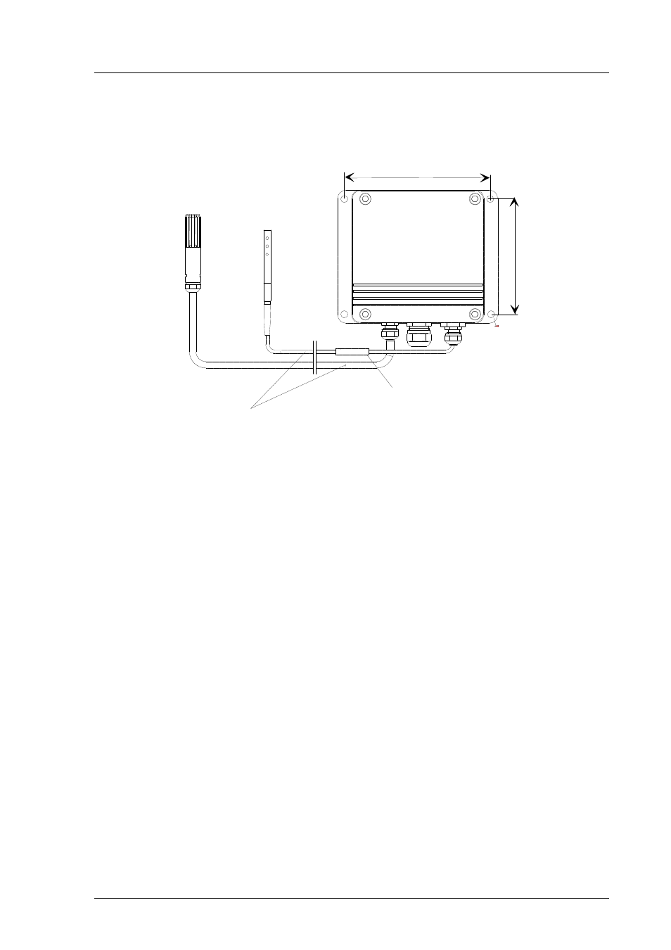
3.2.1 Mounting the HMP243
Cable length 2000,
5000 or 10000 mm
T-sensor head
(optional)
humidity
sensor head
Sliding PTFE-sleeve for flange installation
and cable-gland installation
ø6.5
104
133
Figure 3.1
HMP243 transmitter with a humidity sensor head and an
additional T sensor head
When mounted on the side of a duct or channel, the sensor head must be in-
serted from the side (see Figure 3.2). If this is not possible and the sensor head
must be inserted from the top, the point of entry must be carefully insulated.
NOTE
The two sensor heads should be installed so that the
humidity sensor head does not warm the T sensor head,
i.e. the T sensor head is installed closer to the process
flow. When the RH reading is required, always install
the T sensor head in the place where you need the
reading from.
The HMP243 can be installed in ducts and channels with the help of the in-
stallation kit; the kit consists of a flange, a supporting bar for the sensor head
cable and screws for attaching the flange to the wall of a duct. With the help
of the installation kit the distance between the sensor head and the channel
wall can be easily adjusted. The range of adjustment is 100...320 mm; the
distance is measured from the tip of the sensor head to the flange.