APC iSCSI SATA II User Manual
Page 16
[16]
2.3 Identifying Parts of the iSCSI RAID Subsystem
The illustrations below identify the various parts of the subsystem.
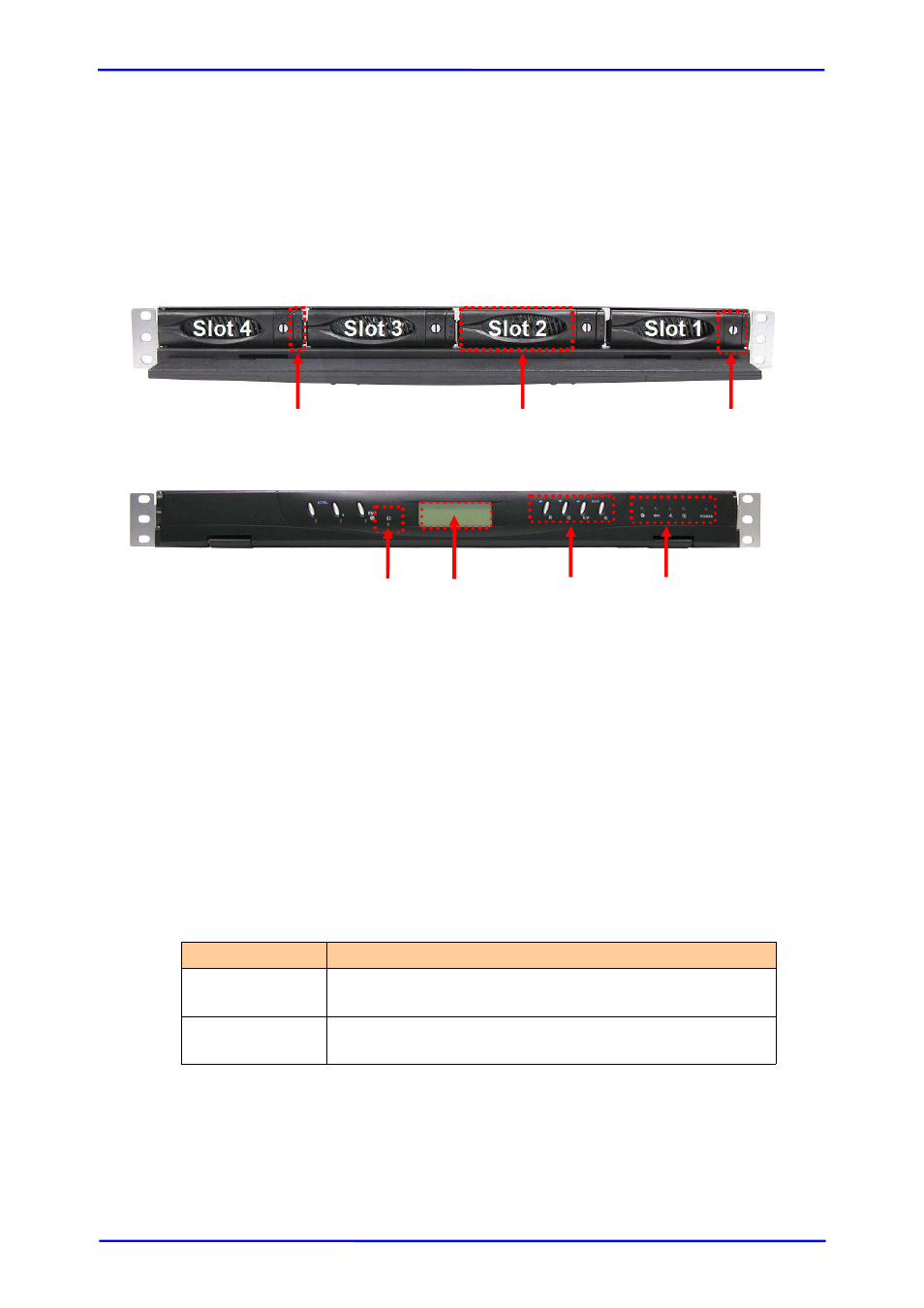
2.3.1 Front View
1 Carrier Open Button –
Use this to open the disk tray. Press the button to
open. This button also shows the Lock Indicator
.
When the Lock Groove is horizontal, this indicates that the Drive Tray is
locked. When the Lock Groove is vertical, the Drive Tray is unlocked. Lock
and unlock the Drive Trays by using a flat-head screw driver.
2 Tray Lever – Use this to pull out the disk tray.
3 HDD Status Indicator
Every Drive Tray contains two LEDs for displaying the HDD status.
Parts
Function
HDD Status
LED
Green LED indicates power is on and hard drive status
is good for this slot. Red LED indicates no hard drive.
HDD Access
LED
LED will blink blue when the hard drive is being
accessed.
4 Activity LED – This LED will be blinking Blue when the controller is busy or
data is being accessed.
4 5 6 7
3
2
1