AMX Distribution Matrix Octaire User Manual
Page 37
Installation and Setup
33
Octaire Instruction Manual
2.
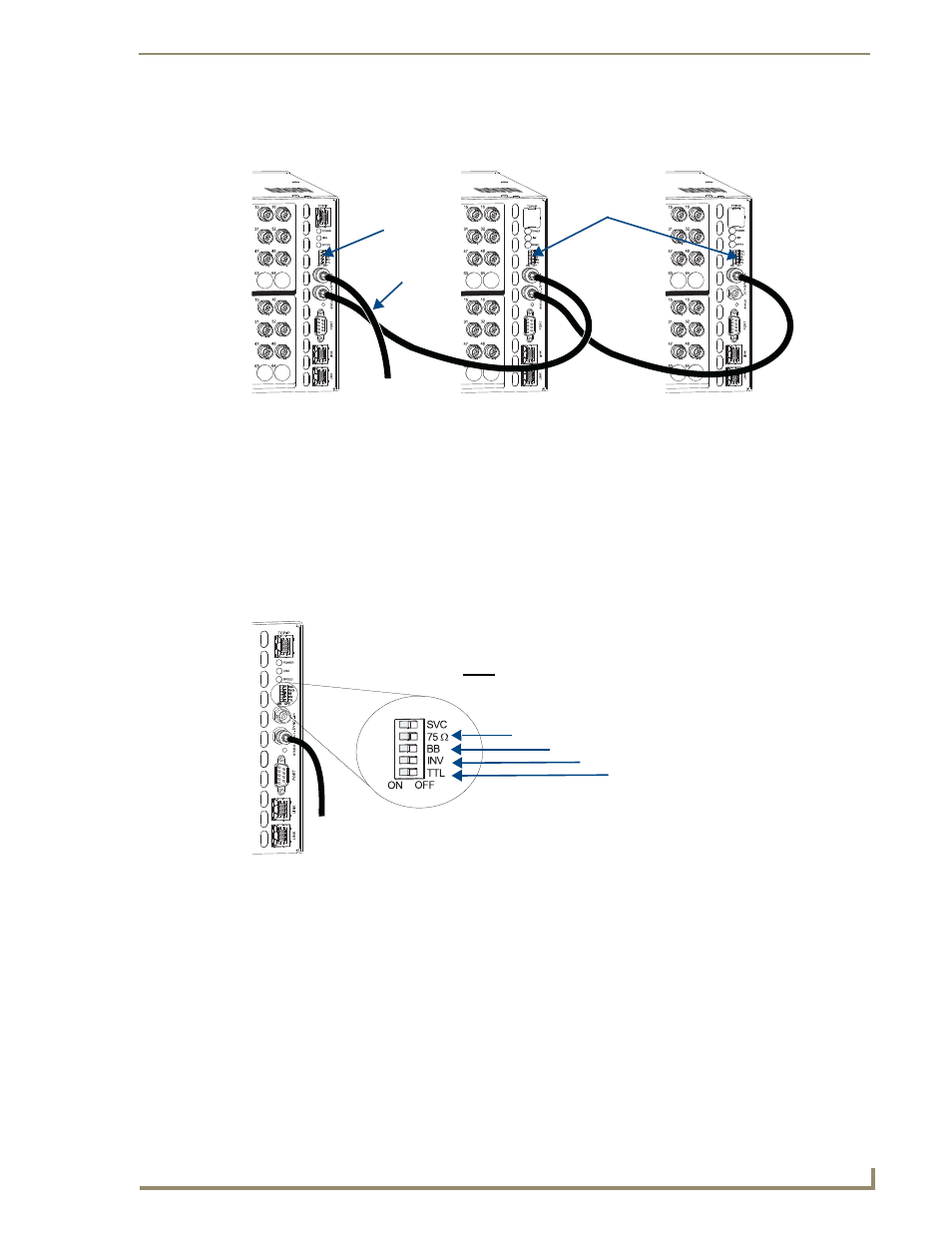
Attach a cable to the Sync Out connector on the primary enclosure (FIG. 24).
3.
Attach the other end of the cable to the Sync In connector on the second enclosure.
4.
For all additional video enclosures, cable the Sync Out connectors to the Sync In connectors.
5.
Flip the appropriate VIS toggle switches on each enclosure to the left for “on” and right for “off”
according to the information provided below.
VIS Toggle Switches
The VIS toggle switches on the rear of the primary enclosure must be set to agree with the type of signal
used for Vertical Interval Sync. On any secondary enclosure(s), the TTL toggle switch is the only VIS
switch set to “on.”
Primary Enclosure
The setting for the VIS toggle switch on the primary enclosure (the one with the control panel) depends
on the type of external sync source.
If the external sync source is a Blackburst generator or NTSC composite video, set the BB
(Blackburst) switch to “on” (be sure the TTL switch is “off”).
If the external sync signal is a TTL composite sync input, set the TTL switch to “on” (be sure
the BB switch is “off”).
Note: If you need to provide a 75 ohm load for the external source, set the 75 ohm switch on
the primary enclosure to “on” to provide the load. (When the 75 ohm switch is “off,” the input is
terminated at high-impedance.)
FIG. 24
Sync signal routed to multiple enclosures
FIG. 25
VIS toggle switches
Flip appropriate
Primary Enclosure
with Control Panel
Secondary Enclosure
Secondary Enclosure
From external
sync source
VIS toggle switches
(see below)
Flip appropriate
VIS toggle switches
75
Ω (Termination)
BB (Blackburst)
INV (Inverted)
–
set to “off” at all times
TTL (Transistor-Transistor Logic)
Note: The top toggle switch, labeled SVC, is the Service switch (see page 36).
This switch must be set to the right for normal operation.