AMX Distribution Matrix Octaire User Manual
Page 32
Installation and Setup
28
Octaire Instruction Manual
3.
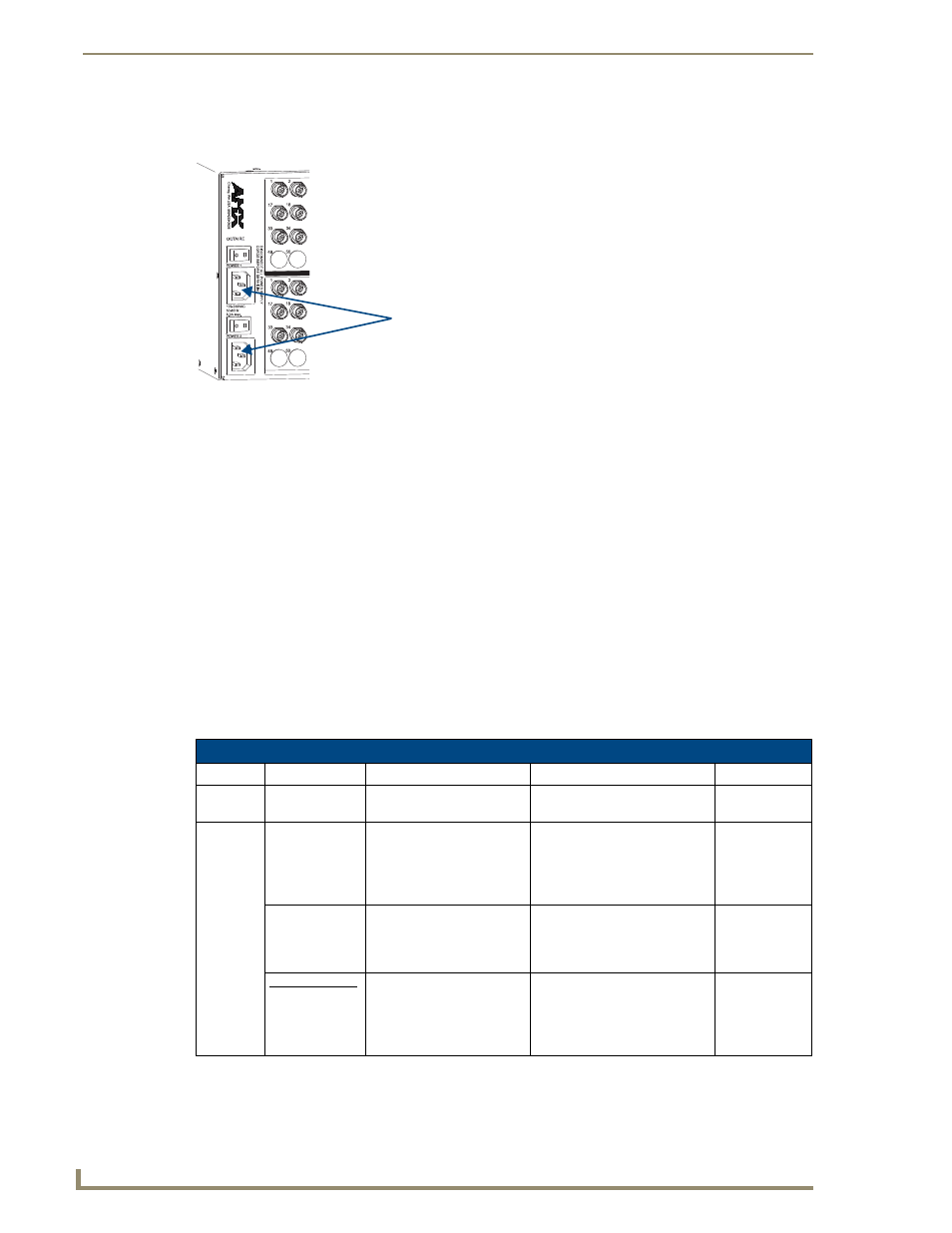
Plug power cords into the power receptacles on the enclosure (repeat for additional enclosures in
multi-enclosure systems). Press the “l” side of both power switches on each enclosure (FIG. 20).
4.
Plug the other end of each power cord into a power strip that is turned off (we recommend using
a 30 A power strip).
5.
Turn on the power strip and wait 30 seconds.
The Power indicator on the front of the panel illuminates green (both redundant power supplies are
working). If only one power supply is working, the Power indicator will illuminate red (check
power connections and switches).
6.
Optional – Apply power to the external control device/system.
7.
Apply power to the source and destination devices.
The LCD on the control panel illuminates and displays the menu screen.
8.
The system is ready for a test switch (see page 30, “Executing a Test Switch”).
The system is ready to execute a test switch using the control method of your choice. For startup
information on specific types of control before executing a test switch, see page 30.
Indicator Lights at Startup
When the enclosure powers up, the indicator LEDs will respond as follows:
Important: If the indicator lights do not respond with a normal display as stated above, check power
connections and switches, and then contact technical support (see page 31).
FIG. 20
Plug power cords into power receptacles
Octaire LED Indicators
LED
Indicates
Normal Display
Cautionary
Enclosure
Front
Power
System power
Constant green
Constant red
Enclosure
Rear
TCP/IP –
Power
–
Link
–
Speed
System receiving power
Active link status with server
Speed status is either
100 Mbps or 10Mbps
On
On
On – Speed status is 100 Mbps
Off – Speed status is 10 Mbps
Status
System status
Constant green during power
up, then blinking green at 1/2
second on/off intervals
Blinking red or
red/green at
1/2 second
on/off intervals
Linked Systems
Link –
Amber
–
Green
Activity between enclosures
Active link status
Amber – Blinks with activity
Green – On
Power receptacles
LEDs at Startup