Caution, Before installation, Initial setup – GReddy e-Manage Ultimate Installation Manual User Manual
Page 10
4. Before Installation
Caution
9
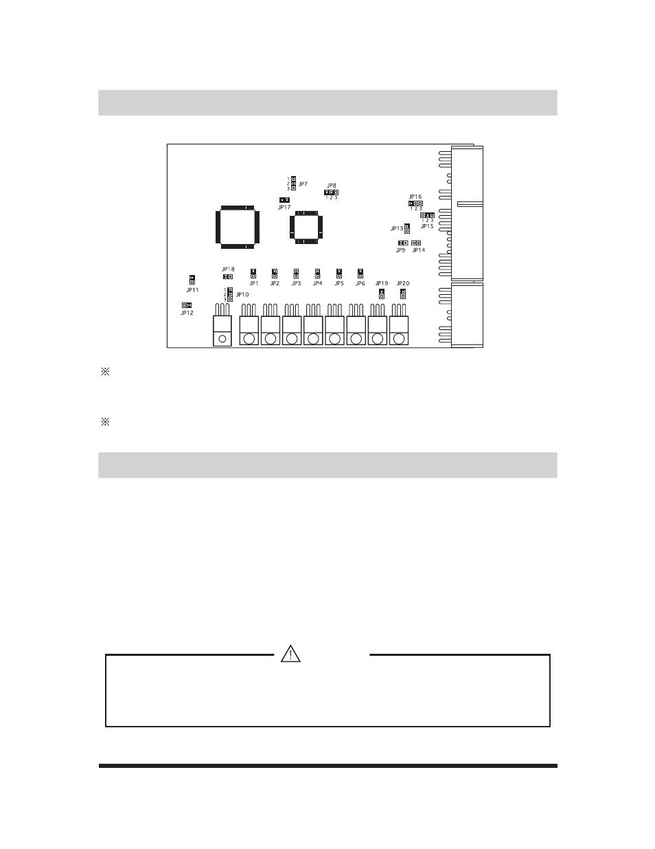
3. Initial Setup
Jumper Location
When Jumping “1-2” or “2-3” make sure to match the pin numbers printed on the circuit board
at the coresponding jumper locations.
For “OPEN” make sure the jumper is not jumping the pins at the corresponding jumper
locations.
When setting jumpers to “OPEN” make sure to place the jumper on to one side of the pin to
prevent loosing the jumpers.
1. Disconnect the negative terminal of the battery.
2. Locate the facotry ECU and disconnect the ECU harness connectors. Refer to the ECU location
Chart on the back of this manual.
3. Follow the wire diagram for the specific vehicle list on the back of this manual, and connect each
harnesses.
4. Inspect all connections and reconnect the ECU harness connector. Reconnect the negative
terminal of the battery.
Tools needed
• wire cutter
•Crimper
•Solder and Soler Iron
•Shrink Tube and Electrical Tape
•When making any wire connections, DO NOT use any crimp connector or tapping
connectors. These connectors will cause poor connections.
•Only use the provided connectors with proper tools or solder all wire connections.