Pc 5150, Rmc 7150 – Acnodes RMC 7150 User Manual
Page 32
© Copyright 2011 Acnodes, Inc.
All rights reserved. Product description and product specifications
are subject to change without notice. For latest product information,
please visit Acnodes’ web site at
PC 5150
15-inch touch panel PC
14628 Central Blvd,
Chino, CA91710
tel:909.597.7588, fax:909.597.1939
32
RMC 7150
14” short depth rack server
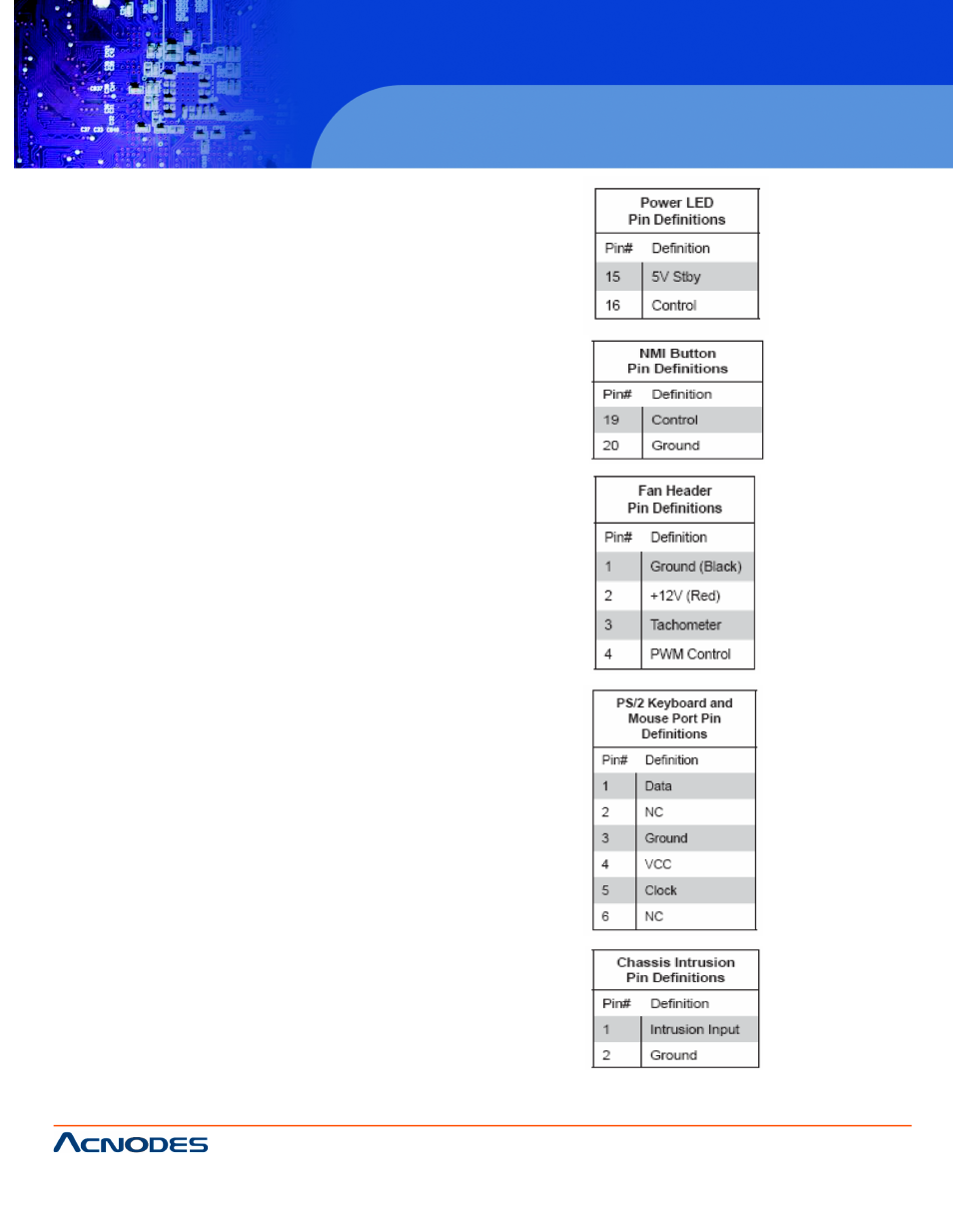
Power on LED
The Power On LED connector is located
on pins 15 and 16 of JF1. This connection
is used to provide LED indication of power
being supplied to the system. See the
table on the right for pin definitions.
NMI Button
The non-maskable interrupt button header
is located on pins 19 and 20 of JF1. Refer
to the table on the right for pin definitons.
Fan Headers
There are six fan headers. All are 4-pin
fans but are backward compatible with
traditional 3-pin fans. FAN1 is for the
CPU1 heatsink and FAN2 is for the
CPU2 heatsink. See the table on the
right for pin definitions.
ATX PS/2 Keyboard and PS/2
Mouse Ports
The ATX PS/2 keybaord and the PS/2
mouse are located on the rear IO panel.
The mouse port is above the keyboard
port. See the table on the right for pin
definitions.
Chassis Intrusion
The Chassis Intrustion is designated JL1.
See the board layout for the location of
JL1 and the table on the right for pin
definitions.