Rmc 7150, 14” short depth rack server – Acnodes RMC 7150 User Manual
Page 15
14628 Central Blvd,
Chino, CA91710
tel:909.597.7588, fax:909.597.1939
© Copyright 2011 Acnodes, Inc.
All rights reserved. Product description and product specifications
are subject to change without notice. For latest product information,
please visit Acnodes’ web site at
RMC 7150
14” short depth rack server
15
CHAPTER 3 SYSTEM INTERFACE
3.1 Overview
There are several LEDs on the control panel to keep you constantly informed of the overall status of the system as well as the
activity and health of specific components. There are also two buttons on the chassis control panel. This chapter explains the
meanings of all LED indicators and the appropriate respnse you may need to take.
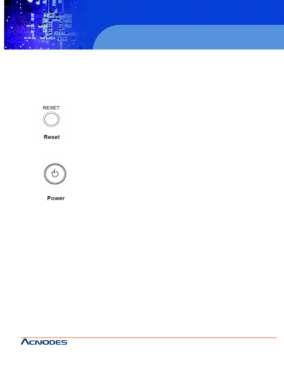
3.2 Control Panel Buttons
There are two push buttons located on the front of the chassis: a reset button and a power on/offbutton.
The reset switch reboots the system
This is the main power switch, which is used to apply or turn off the main system power. Turning off system power with this
button removes the main power but keeps the standby power supplied to the system.