Lokar Electric Kickdown Kit TH400 User Manual
Page 2
INS0004 Rev. 05/08/14
Page 2
© 2004 Lokar, Inc.
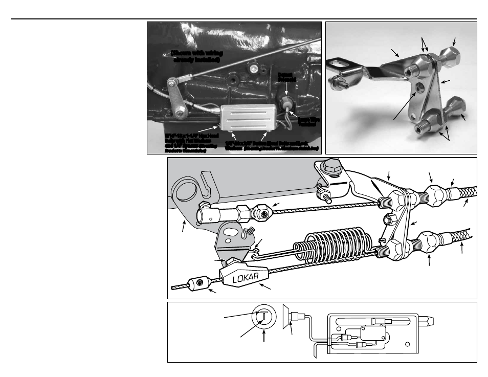
Step 7: The tear drop (not included, part of the Carburetor Bracket
& Spring Kit) will be attached to the carburetor throttle arm
by the hex carb fitting. Separate the hex carb fitting from
the kickdown throttle body fitting. Install the hex carb fitting
and the tear drop onto the carburetor throttle arm as shown
in
Fig. 6. Hook the return springs (not included, part of the
Carburetor Bracket & Spring kit) to the tear drop. Snug the
hex nut down, and then back it off just far enough that the
tear drop can rotate freely.
Step 8: Separate the aluminum switch box from the mounting bracket
by removing the two 1/4"-28 x 3/8" button head bolts.
Step 9: Make sure the spring is still in place on the inner wire, and
re-install the inner wire into the kickdown cable housing.
Position the slide trigger back into its slot in the aluminum
switch box.
Step 10: Feed the wires (not included) through the rubber grommet
into the aluminum switch box, and install the two small wire
terminals onto the ends of the wires. Connect both of the
wires to the switch terminals. It does not matter which wire
is connected to which terminal.
Step 11: Reinstall the back cover onto the aluminum switch box,
using the #10-32 x 1/2" button head bolts and lock washers
you removed earlier. Then reinstall the aluminum switch box
onto the mounting bracket, using the 1/4"-28 x 3/8" button
head bolts and lock washers you removed earlier.
Step 12: Connect one of the wires from the aluminum switch box to a
switched power source with a 5 amp or greater fuse. Install
the remaining large wire terminal onto the end of the other
wire, and connect it to the vertical terminal on the detent
solenoid on the transmission.
Fig. 7
NOTE: The detent solenoid may have either one or two terminals.
Step 13: Before connecting the inner wire to the carburetor, make
sure that the throttle linkage is properly adjusted. Verify at
the carburetor that the throttle is wide open while you have
a helper hold the accelerator pedal to the floor. Once you
are sure that the throttle linkage is adjusted correctly, slide
the kickdown throttle body fitting onto the kickdown cable
inner wire, and connect the kickdown throttle body fitting to
the hex carb fitting.
Step 14: This step will also be much easier with a helper. Slide the
kickdown cable end stop onto the inner wire. Move the
throttle to wide open and hold it there while pulling the
kickdown inner wire as tight as possible. Slide the cable
end stop up against the kickdown throttle body fitting
and tighten the set screw using the supplied 5/64" Allen
wrench. Release the throttle.
When the kickdown cable is properly adjusted you should be
able to open the throttle to the wide open position without
interference from the kickdown cable; and with the throttle
wide open, you should not have any slack in the kickdown
cable. Minor adjustments can be made using the kickdown
cable adjuster on the carburetor bracket.
Double check to be sure that all carburetor, throttle and
kickdown linkage operates freely without binding and that
the throttle returns to the closed position when the pedal
is released, then test drive. Once the kickdown cable is
correctly adjusted and operating properly you can cut off the
excess inner wire, leaving about 1/2" extending beyond
the cable end stop to allow for future adjustment if needed.
TH400 Electric Kickdown Kit Installation Instructions
Carburetor Bracket
(not included)
Adjuster Nuts
(not included)
Throttle Cable
Adjuster
(not included)
Kickdown
Mounting
Bracket
Adjuster Nuts
Kickdown
Cable
Adjuster
#8-32 x 1/2"
Button head Bolt
with Nylock Nut
5/16"-18 x 1-1/4" Hex Head
Bolts with Flat Washers
and 1/4" Spacers
(Mounting
Bracket to Transmission)
Detent
Solenoid
Large Wire
Terminal
1/4"-28 x 3/8" Button Head Bolts and Lock
Washers
(Mounting Bracket To Aluminum Switch Box)
Fig. 5
Fig. 6
Fig. 7
Kickdown Kit shown installed with Lokar Throttle Cable
(not included)
and Lokar Carburetor Bracket and Springs
(not included)
Kickdown
Cable
Housing
Kickdown
Cable
Adjuster
Throttle
Cable
Housing
Ferrule
Throttle Cable
Adjuster
Carburetor Bracket
Carburetor Base
Carburetor
Throttle Arm
Kickdown
Mounting
Bracket
Tear Drop
Cable End Stop
Kickdown
Throttle Body
Fitting
Hex Carb
Fitting
Carb End
Fig. 4
(Shown with wiring
already installed)
Side View of
Trans Terminal
Trans
Terminal
Key On 12 Volt Power
Back View of Switch Box
Wrong
Terminal
Right Terminal