Lokar Blower Drive Throttle Cable User Manual
Page 2
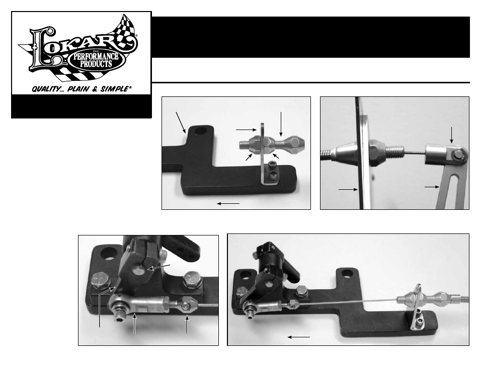
Step 9: At the engine end of the blower drive throttle cable, slide the
cable wire adjuster you removed earlier onto the end of the
inner wire, all the way up to the throttle cable adjuster. Cut
off inner wire approximately 1/2" away from the splined arm.
Slide the cable wire adjuster back out to the end of the inner
wire and snug down the set screw. Install the cable rod end
onto the cable wire adjuster.
Fig. 5
Step 10: Install the remaining #10 lock washer onto the #10-24 x
1" socket head cap screw. Then install one of the #10 flat
washers against the lock washer. Insert the socket head
cap screw through the rod end and install another #10 flat
washer between the rod end and the splined arm. (
NOTE: If
you are installing a Lokar Kickdown cable at the same time,
the blower kickdown bracket goes in between the flat washer
and the splined arm). Install the socket head cap screw in
the threaded hole that is closest to the pivot.
Fig. 5
Step 11: Adjust the blower drive throttle cable. Take any slack out of
the blower drive throttle cable with the adjuster nuts. The
throttle pedal should
touch the floor at the
same time the throttle
reaches wide open.
NOTE: Check to make
sure there is no bind-
ing of the blower drive
throttle cable at both
the throttle pedal and
at the throttle linkage
before starting the
engine or driving the
vehicle. Your final
installation should
look like
Fig. 4 and
Fig. 6.
Building American Quality… With A Lifetime Warranty!
10924 Murdock Dr. • Knoxville, TN 37932
TOLL FREE 1-877-469-7440 • (865) 966-2269 • FAX (865) 671-1999 • [email protected] • www.lokar.com
®
Blower Drive Throttle Cable Installation Instructions
Blower Drive Throttle Cable Installation Instructions
INS0123
Rev. 05/08/12
Page 2
© 2012 Lokar, Inc.
Fig. 3
Fig. 4
Blower Base
Bracket
Throttle Cable
Adjuster
Clevis
Firewall
Blower
Cable
Bracket
Adjuster Nut
Adjuster Nut
Lokar Pedal Upper Arm
(not included in Blower
Drive Throttle Cable Kit)
Front
Splined Arm
Cable Rod End
Cable Wire
Adjuster
Pivot
Fig. 5
Fig. 6
Front
Final Installation - Under Hood