Lokar Blower Drive Kickdown Cable User Manual
Page 2
Step 11: Install hex carb fitting and nylock jam nut with kickdown throttle
body fitting in the top hole on the blower kickdown bracket.
Tighten the nylock jam nut.
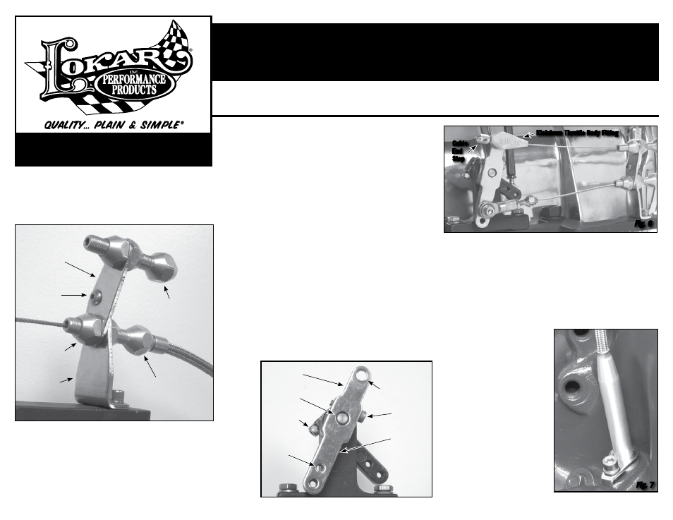
Step 12: Install inner wire through the kickdown throttle body fitting, and
slide the cable end stop onto the inner wire. Position the cable end
stop approximately 2” from the kickdown throttle body fitting and
snug down the set screw just enough to keep it from sliding off.
Step 13: Make final adjustments by holding throttle to wide open and pull-
ing the kickdown inner cable as tight as possible. Move cable end
stop up against the kickdown throttle body fitting and tighten set
screw. When the blower drive kickdown cable is properly adjusted
you will be able to open the throttle to the wide open position and
there will be no slack in
the inner wire.
Double check to be sure
that all carburetor, throt-
tle and kickdown linkage
operates freely without
binding, then test drive.
Once kickdown cable is
correctly adjusted and
operating properly you
can cut off the excess
inner wire, leaving about
1" extending beyond the
cable end stop to allow
for future adjustment.
When finished, the
installation should look
like
Fig. 6 and Fig. 7.
© 2012 Lokar, Inc.
INS0124
Rev. 05/23/12
Page 2
Building American Quality… With A Lifetime Warranty!
10924 Murdock Dr. • Knoxville, TN 37932
TOLL FREE 1-877-469-7440 • (865) 966-2269 • FAX (865) 671-1999 • [email protected] • www.lokar.com
®
Blower Drive Kickdown Cable Installation Instructions
Blower Drive Kickdown Cable Installation Instructions
For TH200, TH350, TH700-R4, TH200-4R, and 4L60
For TH200, TH350, TH700-R4, TH200-4R, and 4L60
Step 5: Route the throttle cable inner wire and the throttle cable adjuster
through the bottom hole in the kickdown mounting bracket.
Reinstall the front throttle cable adjuster nut, and connect (or
reconnect) the throttle cable inner wire. Attach kickdown mount-
ing bracket to blower cable bracket as shown in
Fig. 4, using the
#8-32 x 1/2” button head bolt and nylock nut.
Step 6: Route kickdown cable housing up to the kickdown cable
adjuster. If the cable housing is braided stainless steel, slide the
ferrule back towards the transmission, away from the end that is
being cut. DO NOT remove the ferrule from a braided stainless
steel housing! If the housing is black universal, remove the fer-
rule. Add 1" extra and cut the kickdown cable housing to desired
length. Make sure that the inner wire is removed from the cable
housing before cutting!
Step 6: (continued) If the cable housing is braided stainless steel, wrap tape
around the area to be cut and use an abrasive cutoff saw or fine-
toothed hacksaw. If the kickdown cable has a black universal housing,
cut the cable housing with heavy duty 8” diagonal cutting pliers or a
hacksaw. Lokar recommends Klein brand Diagonal Cutting Pliers, #
D2000-28 available at The Home Depot or through W. W. Graingers,
Part # 4A838.
After cutting the cable housing, put the ferrule back in place at the
end of the cable housing. Insert the cable housing and ferrule into the
kickdown cable adjuster.
Step 7: Remove the kickdown cable housing from the transmission. Re-install
the inner wire into the blower drive kickdown cable housing.
Step 8: On the trans tube at the transmission end of the blower drive kick-
down cable there will be either one or two o-ring grooves. TH350 &
TH200 use one o-ring, and the TH700R4, TH200-4R, and 4L60 use
two o-rings. Lightly lubricate the kickdown cable o-ring(s) with clean
transmission fluid and slide the o-ring(s) into the groove(s) on the trans
tube. To help prevent leakage add a small amount of silicone sealant
(RTV) around the trans tube above the top o-ring.
Fig. 2
Step 9: Insert the hook on the transmission kickdown rod into the hole on the
end of the kickdown cable inner wire. Install the transmission tube into
the transmission, and secure with the tube hold down clip and bolt.
Step 10: Install the blower kickdown bracket onto the splined arm on the
blower throttle linkage, with the two holes at the bottom. The blower
kickdown bracket is positioned by the blower linkage pivot shaft and
attached using the throttle cable bolt. If the blower linkage pivot
shaft does not protrude out far enough to align the blower kickdown
bracket, it will be necessary to adjust the position of the splined arms
on the pivot shaft by loosening the pinch bolts and repositioning parts
as needed.
Fig. 5
Kickdown
Mounting
Bracket
Blower Kickdown
Bracket
Hex Carb Fitting
with Nylock Jam
Nut goes here
Blower Linkage
Pivot Shaft
Pinch Bolt
Pinch Bolt
Splined Arm
(Behind Blower
Kickdown Bracket)
Throttle Cable
Bolt goes here
Kickdown Cable
Adjuster
Throttle Cable
Adjuster
#8-32 Button
Head Bolt with
Nylock Nut
Front Throttle
Cable Adjuster Nut
Blower Cable
Bracket
Fig. 4
Fig. 5
Cable
End
Stop
Fig. 6
Fig. 7
Kickdown Throttle Body Fitting