Lokar Anchor-Tight Locking Flexible Transmission Dipstick User Manual
Lokar For the car
Building American Quality… With A Lifetime Warranty!
General Installation Notes:
Please read instructions completely before beginning the installation. If you
have any questions please call.
Disconnect negative battery cable and set parking brake or chock vehicle
wheels before beginning the installation.
TOLL FREE 1-877-469-7440 • [email protected] • www.lokar.com
®
Anchor-Tight Locking Flexible Transmission Dipstick
Installation Instructions
INS0075 Rev. 01/23/14
Page 1
© 2007 Lokar, Inc.
Anchor-Tight Locking Flexible Transmission Dipstick
Installation Instructions
NOTE: The dipstick is designed for transmissions with “push in” style dipsticks.
Each transmission dipstick has been calibrated for the specific transmis-
sion application.
The standard
Firewall Mount dipstick is approximately 26" in length, but can
be special ordered in lengths up to 48". It allows the dipstick to be mounted
to the firewall or anywhere desired in the engine compartment. The
Transmount
dipstick varies in length according to the transmission application and mounts
on the bell housing. The Firewall Mount is the most versatile and is used where
there is little room in the engine compartment.
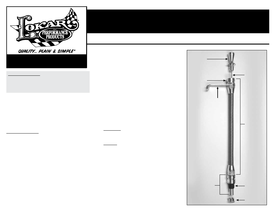
Refer to Fig. 1 for the component names.
How to Use Locking Mechanism:
To insert or remove the dipstick handle and inner measuring cable, slide the
spring-loaded retaining sleeve downwards away from the handle and hold while
inserting or removing the handle and inner measuring cable. See
Fig. 2.
The Lokar Transmount and Firewall Mount dipstick tubes also have a locking
quick disconnect fitting on the bottom so that you can remove the dipstick
tube assembly for easier installation or removal of the transmission. To remove
the dipstick tube assembly from the transmission, push the spring loaded
retaining sleeve downwards and hold, while pulling up on the dipstick tube
assembly.
A transmission storage plug is included with the Transmount and Firewall
Mount dipsticks. Place this storage plug into the pan fitting when the transmis-
sion is being transported, installed or removed. This helps prevent fluid spill-
age.
Fig. 3 Additional pan fittings and plugs are available separately.
NOTE: DO NOT remove any nuts securing the braided stainless steel hose to the
dipstick tube assembly.
DO NOT disassemble the spring loaded retaining
sleeve mechanism.
Step 1: Clean the dipstick opening on the transmission, making sure it is free
from all debris or burrs.
Step 2: Drain the transmission fluid and remove the transmission fluid pan.
Step 3: Remove the pan fitting from the bottom end of the new Lokar dipstick
tube assembly. Remove the pan nut from the pan fitting. Lubricate the
rubber push-in grommet with clean transmission fluid. Install the pan
fitting and rubber push-in grommet (as received) into the transmission.
(This should be a tight fit). Screw the pan nut onto the pan fitting and
torque to 20 ft.-lbs.
Do Not Over Tighten! Fig. 4
TH400 Note: When installing the pan nut on a TH400, rotate the nut
until one of the flats on the nut is parallel to the pan rail. This will allow
the pan to be installed without interfering with the nut.
Powerglide Note: A tapered washer is supplied with all Powerglide dip-
sticks. This washer needs to be installed on the pan fitting and rotated
until the pan nut has a square surface to tighten up against. Torque to
20 ft.-lbs.
Do Not Over Tighten!
Ford and Chrysler Note: Some transmission cases have limited space in
this area and there will not be enough room to turn the nut or retaining
tab. You will need to screw the pan fitting into the nut or retaining tab
instead. This can be done by using the supplied 1/2" hex installation
tool. Insert the end of the installation tool with the largest chamfer into
the top of the pan fitting. Push it down until it slips past the o-ring
inside the fitting. Use a 1/2" socket to rotate the pan fitting into the nut
or retaining tab. Torque to 20 ft.-lbs.
Do Not Over Tighten!
Step 4: Insert the dipstick tube assembly into the pan fitting, making sure it
clicks into place. The retaining sleeve
MUST be pushed down in order
for the dipstick tube assembly to be fully inserted.
Step 5: FiREwALL MOUNT, Route the dipstick tube assembly to the desired loca-
tion (firewall, inner fender, etc.) and install the mounting bracket using
two screws of your choice (not included). Make sure the dipstick tube
assembly is not touching the exhaust at any point.
Step 5: TRANSMOUNT, Install the mounting bracket onto the bell housing using
the appropriate existing bell housing bolt. Make sure the dipstick tube
assembly is not touching the exhaust at any point.
Powerglide Note: Some aftermarket Powerglide cases require a spacer
to be used between the case and the Lokar mounting bracket. A 3/16"
aluminum spacer is provided in the kit for this purpose. Also verify that
the mounting bolt being used to hold the bracket and spacer in place is
the correct length.
Step 6: Using an automotive funnel, fill the transmission with the appropriate
amount of fluid. Return the dipstick handle and inner measuring cable
into the dipstick tube assembly, being sure that the handle is snapped
down in its locked position when checking the fluid level. The retaining
sleeve
MUST be pushed down in order for the handle and inner measur-
ing cable to be fully inserted. This will ensure that the transmission
fluid is at the appropriate level.
Fig. 5
NOTE: Be sure to follow the transmission manufacturers recommended
procedure when checking the transmission fluid level (engine running or
not, fluid hot or cold, shifter in a particular position, etc.).
Pan Nut
Pan
Fitting
Mounting
Bracket
Typical transmount
dipstick shown as
an example only.
The mounting
bracket and pan
fitting will vary by
application.
Retaining
Sleeve
Handle
Grommet
Dipstick
Tube
Assembly
Inner
Measuring
Cable
Fig. 1
®
®