Lokar Throttle Pedal For 1967-1972 C-10 Chevrolet & GMC User Manual
Lokar For the car
Building American Quality… With A Lifetime Warranty!
General Installation Notes:
Please read instructions completely before beginning installation. If you
have any questions please call.
Before starting installation, scotch vehicle tires to avoid accidental move-
ment of the vehicle. Do not attempt to install this product while the engine
is running. Disconnect negative battery cable before beginning installation.
Make sure the engine, transmission, body and frame are properly grounded.
We recommend applying anti-seize lubricant to all aluminum threads before
final assembly.
The Lokar Throttle Pedal is designed to work with a Lokar Throttle Cable. A
stock-style throttle cable will not work. If the vehicle has an automatic
transmission, installation of a Lokar Kickdown Kit (if applicable) is strongly
recommended. Lokar Kickdown Kits are application-specific according to the
type of induction system and the transmission model.
1967-1970 Models:
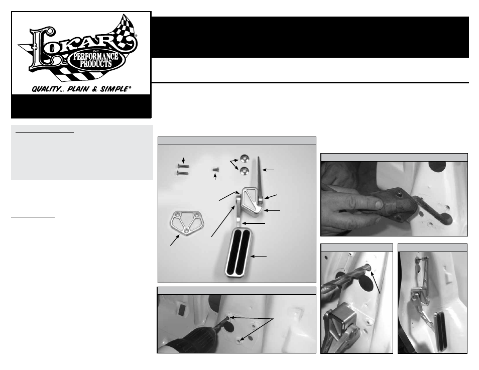
Refer to Fig. 1 for the component names.
Step 1: Remove all of the existing factory throttle linkage from the vehicle.
Step 2: Remove the original throttle pedal footpad and mounting studs from
inside the vehicle. Remove the throttle pedal arm assembly from the
outside of the firewall.
Fig. 2
Step 3: Using a 17/64" (0.2656") drill bit, drill out ONLY TWO of the three
original mounting holes where the factory pedal was mounted to the
firewall. The arrows in
Fig. 3 show which holes are to be drilled out
(photo taken from INSIDE the passenger compartment).
Step 4: On the new Lokar pedal assembly, remove the 1/4"-20 x 1/2" flat
head bolt and aluminum end washer from the pedal pivot shaft on
the left side of the pedal base using a 5/32" Allen wrench. Slide the
lower pedal arm and pedal pad off of the pedal pivot shaft.
Step 5: Position the throttle pedal base with the upper pedal arm on the
inside of the firewall. The two bolt holes in the pedal base should be
aligned with the two holes you drilled out earlier.
Install the firewall trim plate to the outside of the firewall using the
supplied flat head bolts. The two 1/4"-20 x 1-1/4" flat head bolts will
pass through the firewall trim plate first, then through the firewall
holes you drilled out earlier, and then thread into the Lokar throttle
pedal base. The 1/4"-20 x 5/8" flat head bolt will go through the third
hole in the firewall trim plate and thread into the original mounting
hole on the firewall that you did not drill out.
Step 6: The Lokar throttle cable will be installed into an existing hole in the firewall.
This hole is approximately 5" above the pedal pivot shaft and has a factory fire-
wall pad retaining button in the hole. In some cases it might require some trim-
ming of the factory firewall pad. Drill the existing hole to 1/2" diameter.
Fig. 4
Step 7: Install the throttle cable firewall fitting into the hole in the firewall with the sup-
plied bezel washers (one washer on each side of the firewall). Adjust the firewall
fitting so that it is in line with the hole in the upper pedal arm. Tighten the
adjuster nut on the firewall fitting. Refer to the Lokar throttle cable instructions
to complete the cable installation.
10924 Murdock Dr. • Knoxville, TN 37932
TOLL FREE 1-877-469-7440 • (865) 966-2269 • FAX (865) 671-1999 • [email protected] • www.lokar.com
®
1967-1972 C-10 Chevrolet & GMC Throttle Pedal
Installation Instructions
1967-1972 C-10 Chevrolet and GMC Throttle Pedal
Installation Instructions
INS0056 Rev. 11/14/12
Page 1
© 2012 Lokar, Inc.
Step 8: After the throttle cable is connected to the upper pedal arm and to the
carburetor or throttle body, open the throttle to wide open position and
hold it there. Reinstall the lower pedal arm and pedal pad onto the pedal
base so that the pedal is in the "floored" position. This will ensure that
the throttle is reaching the wide open position at the same time as the
throttle pedal reaches the end of its travel. It may require some trial and
error to get the lower pedal arm positioned correctly. Reinstall and tighten
the 1/4"-20 x 1/2" flat head bolt with the aluminum end washer onto the
pedal pivot shaft. A completed installation is pictured in
Fig. 5.
NOTE: Check to make sure that there is no binding of the cable at both
the pedal and at the carburetor or throttle body before starting and driving
the vehicle.
Fig. 1
1967-1970 Models Only
1967-1970 Only
Fig. 2
1967-1970 Only
Fig. 3
1967-1970 Only
Fig. 4
Fig. 5
1967-1970 Only
1/4"-20 x 1-1/4"
Flat Head Bolts
1/4"-20 x 5/8"
Flat Head Bolt
Bezel
Washers
Felt
Washer
Firewall
Trim
Plate
Pedal Pad
Photo taken from inside
passenger compartment
Drill using
1/2" Drill Bit
Drill using
17/64" Drill Bit
Lower
Pedal Arm
Pedal
Base
Pedal Pivot
Shaft
Upper
Pedal Arm
1/4"-20 x 1/2"
Flat Head
Bolt with
Aluminum
End Washer