Lokar Eliminator Floor Mount Throttle Pedal User Manual
Lokar For the car
Building American Quality… With A Lifetime Warranty!
General Installation Notes:
Please read instructions completely before beginning installation. If
you have any questions please call.
Before starting installation, scotch vehicle tires to avoid accidental
movement of the vehicle. Disconnect negative battery cable before
beginning installation.
Make sure the engine, transmission, body and frame are properly
grounded. We recommend applying anti-seize lubricant to all alumi-
num threads before final assembly.
The Lokar Eliminator Floor Mount Throttle Pedal is designed to work with a
Lokar throttle cable. Most applications will require a 36" throttle cable. Vehicles
equipped with a fuel injected GM LS, Ram Jet, or Vortec engine will require a 48"
throttle cable.
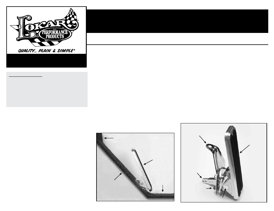
Step 1: Determine your desired mounting location. This throttle pedal is
designed to be mounted on the angled toe board just below the verti-
cal firewall,
NOT on the horizontal part of the floor. Fig. 1 The bottom
edge of the pedal pad should be parallel to the horizontal part of the
floor. Make sure that the location of the pedal bracket, throttle cable,
and cable pull arm will not interfere with any other components such
as brake or fuel lines, clutch linkage, wiring, or exhaust.
Fig. 2
NOTE: If the cable pull arm creates interference because it extends
too far into the engine compartment, Lokar has a 1/2" Throttle Pedal
Spacer available that may be a solution.
Step 2: Remove the pedal pad from the throttle pedal assembly. Be careful
to keep the assembly together while the pedal pad is removed. Lay
the pedal pad on the toe board at the desired location and angle.
Check pedal position for comfort. Mark the position of the pedal pad
on the left side and the bottom of the pedal pad using tape, a scribe
or a marker.
Fig. 3
Step 3: Remove the pedal pad from the toe board.
Step 4: Use the back side of the pedal bracket as a template. Position it flat
on the toe board with the left edge aligned with your vertical mark,
and the bottom left corner 3/4" above your bottom mark.
Fig. 4 Mark
the four (4) bolt holes using a center punch or marker, and also trace
the inside of the rectangular hole onto the toe board.
Step 5: Verify again that nothing is going to interfere with the pedal bracket
and that nothing will be damaged when drilling/cutting the holes. Use a
3/16" drill bit to drill out all four (4) bolt holes.
The best way to cut out the center rectangle is to drill a hole in each
of the 4 corners in the rectangle. Then cut from hole to hole with a die
grinder cutoff wheel.
Step 6: Test fit the pedal assembly for proper location, clearance and angle.
Step 7: Remove the triangular splined bearing block from the cable pull shaft.
Fig. 5
Step 8: Temporarily install the pedal assembly and bracket onto the toe board,
using only two (2) of the four bolts, installed in opposite corners, with
the cable bracket in place.
Step 9: The idle and wide open throttle pedal stops are button head bolts
with jam nuts that are located on the cable pull arm. The one on the
top side is the idle stop, and the one on the bottom is the wide open
throttle stop. Adjust the idle stop out so that the measurement from the
cable pull arm to the top of the button head is about 1/4".
Fig. 6
Step 10: Raise the cable pull arm all the way up until the idle stop makes con-
tact, and reinstall the triangular splined bearing block with the long
flat side at the angle you want the throttle pedal to be at idle.
Step 11: Remove the pedal assembly from the vehicle and reinstall the pedal
pad onto the pedal assembly.
TOLL FREE 1-877-469-7440 • (865) 966-2269 • FAX (865) 671-1999 • [email protected] • www.lokar.com
®
Eliminator Floor Mount Throttle Pedal Installation Instructions
Eliminator Floor Mount Throttle Pedal
Installation Instructions
INS0053 Rev. 09/06/12 RPD 08/29/13
Page 1
© 2012 Lokar, Inc.
Firewall
Throttle Pedal
Assembly
Cable Pull Shaft
Pedal Pad
#10-32 x 3/4" Button
Head Bolt With Nylock
Nut (4 Total)
Horizontal
Part of Floor
Toe Board
Pedal
Bracket
Cable Pull
Arm
Fig. 1
Fig. 2
Step 12: Re-install the complete throttle pedal assembly with the pedal
bracket and all four mounting bolts. Pull the pedal all the way up
against the idle stop, and test for position and comfort. Readjust
if necessary. Once you are satisfied with the position of the pedal,
tighten the jam nut on the idle stop.
Step 13: Attach the throttle cable housing to the pedal bracket, following
the throttle cable installation instructions. Install the throttle cable
inner wire, and attach clevis to the cable pull arm.
Fig. 7 For nor-
mal sheetmetal floors, connect the clevis to the inner hole (closest
to the floor). For fiberglass or other thick floors, connect the clevis
to the outermost hole in the cable pull arm.
Step 14: Adjust the throttle cable so that there is no tension on the inner
wire at idle. Then move the throttle to the wide open position and
hold it there. Adjust the wide open throttle pedal stop (on the
bottom side of the cable pull arm) out so that it touches, to pre-
vent overstressing the pedal, cable, bracket and throttle linkage.
Tighten the jam nut and release the throttle.
NOTE: If the pedal pad contacts the carpet or floor prematurely
and prevents the throttle from reaching the wide open position,
Lokar has a 1/2" Throttle Pedal Spacer available that will help.
Step 15: Verify smooth operation with no binding. Verify that the idle and
wide open throttle stops are adjusted correctly.