Lokar Throttle Pedal Assembly For 1955-57 Chevy, 1967-69 Camaro/Firebird, 1964-67 Chevelle, and 1968-72 Nova User Manual
Throttle pedal assembly installation instructions
1.
2.
3.
4.
6.
7.
4.
9.
3.
14.
13.
12.
12.
10.
11.
15.
5.
8.
Building American Quality… With A Lifetime Warranty!
General Installation Notes:
Please read instructions completely before beginning installation. If you
have any questions please call.
Before starting installation, scotch vehicle tires to avoid accidental move-
ment of the vehicle. Do not attempt to install this product while the engine
is running. Disconnect negative battery cable before beginning installation.
Make sure the engine, transmission, body and frame are properly grounded.
We recommend applying anti-seize lubricant to all aluminum threads before
final assembly.
IMPORTANT APPLICATION INFORMATION: This throttle pedal is designed to replace
rod style throttle linkage only. It will not fit a vehicle that originally came with
cable style throttle linkage from the factory.
The Lokar pedal assembly is designed for use with Lokar Throttle Cables. Stock
style cables will not work. If your vehicle has an automatic transmission, instal-
lation of a Lokar Kickdown Kit (if applicable) is strongly recommended. Lokar
throttle cables and kickdown kits are application-specific according to the type
of induction system and the transmission model.
1955-1957 Chevrolet with big block OR small block with tall valve covers: Lokar
has throttle pedals available with a longer billet upper arm (6-7/16" overall
length) to prevent interference between the engine and the throttle cable.
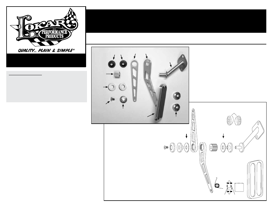
Refer to Fig. 1 for the component names.
Step 1: Remove any existing throttle pedal assembly and linkage components.
Step 2: Disassemble the Lokar Throttle Pedal Assembly by removing the
1/4"-20 x 1/2" flat head bolt
(Fig. 2, #1) from the end of the mounting
shaft
(Fig. 2, #14) and sliding the billet lower and upper arms off of the
mounting shaft.
Step 3: Install the mounting shaft into the firewall from the engine compartment
side using the stock hole where the original throttle linkage was mounted.
Use the original bolts to attach it to the firewall.
Fig. 3
Step 4: Reassemble the Lokar throttle pedal with the billet lower arm (Fig. 2, #6)
pointing down and the billet upper arm
(Fig. 2, #5) pointing up. The billet
upper and lower arms can be switched left to right if needed for clearance
purposes.
Step 5: Push the billet upper arm forward so that it is parallel to the firewall.
Mark the firewall in line with the 3/16" hole on the end of the billet
upper arm. Drill a 5/16" diameter hole through the firewall for the Lokar
throttle cable fitting to mount into.
Note: On 1955-57 Chevys, the two
offset firewall washers
(Fig. 2, #15) will have to be installed on the
firewall (one inside and one outside) and rotated to allow the throttle
cable to go straight through the firewall.
TOLL FREE 1-877-469-7440 • (865) 966-2269 • FAX (865) 671-1999 • [email protected] • www.lokar.com
®
Throttle Pedal Assembly Installation Instructions
For 1955-57 Chevy, 1967-69 Camaro/Firebird, 1964-67 Chevelle,
and 1968-72 Nova
For 1955-57 Chevy, 1967-69 Camaro/Firebird, 1964-67 Chevelle, and 1968-72 Nova
INS0054 Rev. 11/29/12 RPD 04/10/14
Page 1
© 2012 Lokar, Inc.
Throttle Pedal Assembly Installation Instructions
Step 6: Install the Lokar throttle cable assembly according to
instructions supplied with the throttle cable. You may have
to reposition the billet upper arm on the throttle pedal
assembly in order to get the throttle cable adjusted correctly.
Make sure there is no binding in the throttle linkage and
that the throttle returns to the closed position when the
pedal is released.
See
Fig. 4, 5 and 6 for a finished installation.
NOTE: Once the throttle cable is installed, make sure that the
throttle pedal is completely floored when the throttle is wide
open. If the throttle pedal is not completely floored at wide
open throttle, you will need to either change the position of
the billet lower arm on the throttle pedal assembly or install
a pedal stop.
Mounting
Shaft
Lower
Arm
Upper
Arm
Delrin
Bushings
Splined
Bushing
1/4"–20 x 1/2"
Flat Head Bolt
Aluminum
End Washer
Pedal Pad
May or
may not be
included
May or
may not be
included
Offset Firewall Washers
(1955-1957 Chevy only)
Teflon
Washers
(may or
may not be
included)
1. 1/4"-20 x 1/2" Flat Head Bolt
2. Aluminum End Washer
3. Delrin Bushing
4. Teflon Washer
(May or may not be included)
5. Billet Upper Arm
6. Billet Lower Arm
7. Splined Bushing
8. Stainless Pedal Pad Spring
9. Gas Pedal Back
10. Stainless Pedal Pad Pin
11. 3/16" Stainless E-Clips
12. #8-32 x 3/16" Button Head Bolt
13. Pedal Pad
14. Mounting Shaft
15. Offset Firewall Washers
(55-57 Chevy only)
Fig. 1
Fig. 2