Lokar Automatic Trans Mount Shifter Ford C6 User Manual
Page 2
Page 2
© 2003 Lokar, Inc.
Fig. 2
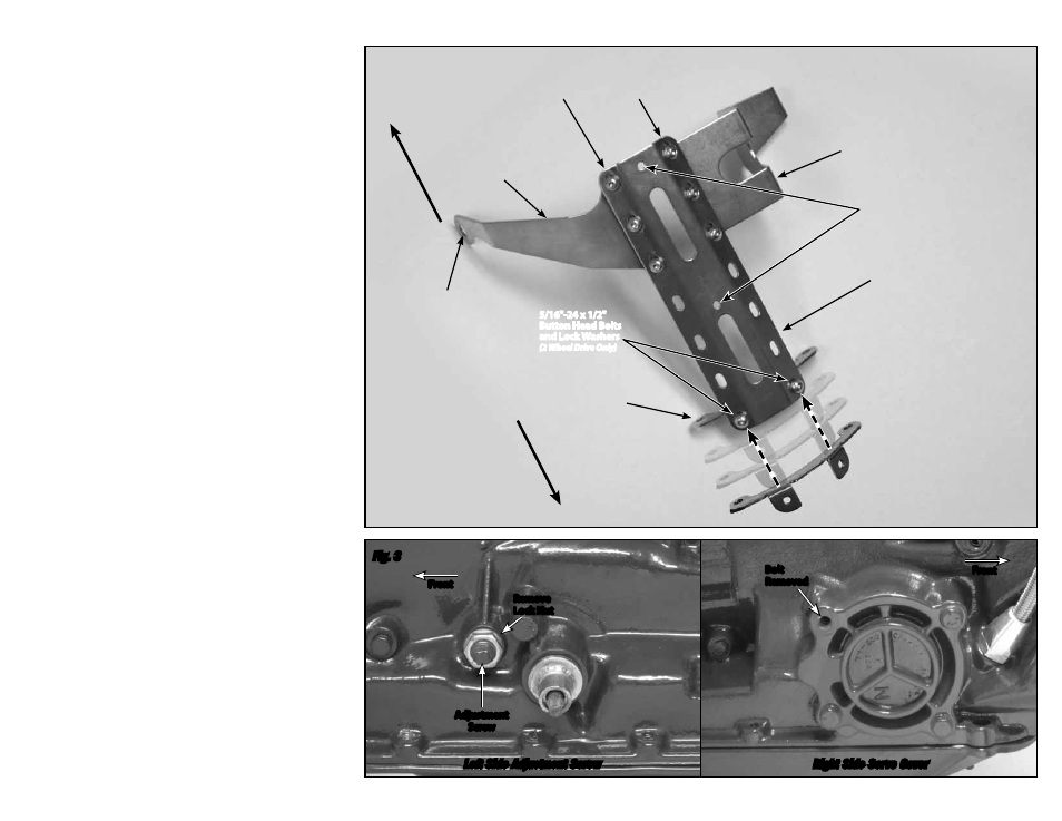
Fig. 3
Step 1: Place the transmission in the Park position. If your vehicle already has a shifter
of any type installed, disconnect all shifter linkage and remove the shifter and
its related hardware (neutral safety switch, back-up light switch, etc.).
Step 2: The Lokar shifter's main plate has two 5/16"-24 tension set screw holes. One
set screw hole is in the center of the main plate, and the other set screw hole
is at one end of the main plate. The main plate will be installed so that the
end of the main plate that has a set screw hole will go to the front (towards the
engine), and the end that does not have a set screw hole will go to the rear.
The left side bracket and right side bracket bolt directly to the front of the main
plate. Attach the side brackets to the underside of the main plate as shown in
Fig. 2, using three 5/16"-24 x 1/2" button head bolts and lock washers on each
side.
DO NOT TIGHTEN AT THIS TIME.
Step 3: (2 Wheel Drive Transmissions) Attach the rear mounting bracket to the underside
of the main plate with two 5/16"-24 x 1/2" button head bolts and lock washers,
using the rearmost pair of holes. The bracket ears should point to the rear end
of the transmission (toward the rear axle) as shown in
Fig. 2. DO NOT TIGHTEN AT
THIS TIME.
(4 Wheel Drive Transmissions) You will not be using the rear mounting bracket.
Step 4: On the left side of the transmission, there is a band adjustment screw with a
lock nut. Use a wrench to hold the adjustment screw still, and carefully remove
the lock nut without disturbing the adjustment screw.
Be sure that you do not
change the adjustment! Fig. 3
On the right side of the transmission, there is a servo cover with four bolts.
Remove the top rear bolt from the servo cover.
Fig. 3
Step 5: (2 Wheel Drive Transmissions) Remove the top two tail housing bolts from the
transmission.
(4 Wheel Drive Transmissions) Install the 5/16"-24 x 5/8" tension set screws
into the tension set screw holes at the front and in the center of the shifter
main plate, and install the jam nuts onto the bottom end of the set screws,
underneath the main plate.
Step 6: Place a small amount of silicone sealer around the band adjustment screw.
Install the mounting bracket assembly onto the transmission by first placing
the left side bracket over the band adjusting screw. Then position the right
side bracket over the servo cover bolt hole, and install the servo cover bolt you
removed earlier. Install the original lock nut back onto the band adjustment
screw.
Again, be sure that you do not change the adjustment! Fig. 4
(2 Wheel Drive Transmissions) Install the two 3/8"-16 x 1-1/2" button head bolts
with lock washers through the rear mounting bracket and into the transmission
at the tail housing.
Step 7: (All) Tighten all of the bolts on the left, right, and rear (2 wheel drive only)
mounting brackets. On 4 wheel drive transmissions, tighten the set screws in
the main plate last (2 wheel drive transmissions do not require set screws in the
main plate).
Fig. 4
(4 Wheel Drive Transmissions) Screw the 5/16"-24 set screws in the main plate
down until they contact the top of the transmission case. Tighten the jam nuts
on the set screws underneath the main plate.
Step 8: You are now ready to position your shifter assembly onto the main plate. There
are several mounting position options from front to rear on the transmission.
If your vehicle already has an opening in the tunnel for the shifter and the
engine is installed in the vehicle, measure from the rear face of the engine
block to the center of your existing shifter opening. If your engine is not yet
installed in the vehicle, measure from the engine mounts to the center of the
existing shifter opening instead.
If the vehicle does not have an existing shifter opening in the transmission
tunnel, decide where you want the shifter to be positioned so that it will be
comfortable and will not interfere with the dash or a bench seat (if applicable).
Mark that spot on the tunnel, and measure as described above.
Mounting Bracket Assembly
Left Side Adjustment Screw
Right Side Servo Cover
Rear of
Vehicle
Front of
Vehicle
Band Adjustment
Screw Hole
Remove
Lock Nut
Adjustment
Screw
Bolt
Removed
Front
Front
Main Plate
5/16"-24 Tension
Set Screw Holes
Left Side
Bracket
Right Side
Bracket
5/16"-24 x 1/2" Button Head Bolts and Lock Washers
(Three Each Side)
Rear Mounting Bracket
(2 Wheel Drive Only)
5/16"-24 x 1/2"
Button Head Bolts
and Lock Washers
(2 Wheel Drive Only)