Lokar Automatic Transmission Shifter GM Tailmount User Manual
Page 2
Page 2
© 2007 Lokar, Inc.
Step 1: If your vehicle already has a shifter of any type installed, disconnect all shifter linkage
and remove the shifter and its related hardware (neutral safety switch, back-up light
switch, etc.).
Step 2: Remove the tailmount bracket from the shifter assembly by removing the four
5/16"-24 x 1/2" button head bolts and lock washers from the curved, slotted holes.
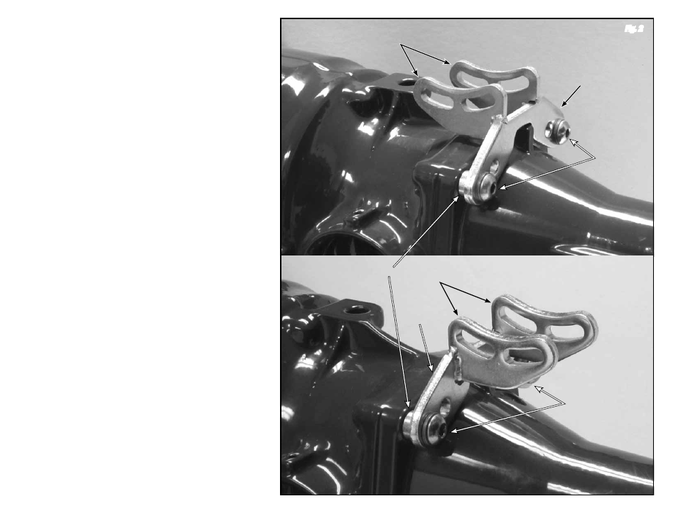
Step 3: The tailmount bracket can be mounted onto the tailhousing in two different positions.
It can be mounted with the welded banana brackets pointing forward towards the
bellhousing, or pointing rearward towards the end of the tailhousing. These two positions
give the shifter approximately a 2" difference from front to back.
Determine which position will work the best for your particular application.
Step 4: Remove the top two tailhousing bolts from your transmission. The Lokar shifter includes
four tailhousing bolts with matching lock washers and two spacers. The button head
bolts are SAE thread, and the hex head bolts are metric. Determine which pair of bolts
(SAE or metric) match the thread on the bolts you removed from your transmission, and
discard the other two bolts and matching lock washers.
Install the lock washers onto the bolts, and insert the bolts into the rear side of the
tailmount bracket. Slide the spacers onto the bolts, and install the tailmount bracket
onto your transmission, with the spacers between the tailmount bracket and the
transmission.
Fig. 2
Step 5: Insert the shifter assembly into the tailmount bracket so that the bolt holes line up
with the curved, slotted holes in the welded banana brackets, and reinstall the
5/16"-24 x 1/2" button head bolts with lock washers.
Fig. 3
Step 6: If you do not already have an opening in the floor in the correct location for the shifter,
measure the distance from the front of the transmission to the center of the shifter.
Transfer that measurement to the vehicle and cut the shifter opening in the floor. If you
are using a Lokar shifter boot, the maximum opening for a round boot is 4" in diameter,
and the maximum opening for a rectangular boot is 4" wide by 5-1/2" long.
Before proceeding any further, the transmission should be installed in the vehicle, with the
vehicle body, driver's seat and dashboard in place.
Step 7: Make sure the two 5/16"-24 x 1/2" button head bolts in the left side of the shifter
assembly on the welded banana bracket are tight. Move the shifter through all the gear
positions. Make sure that the shifter lever and knob do not come in contact with the
dash or the seat. The shifter assembly can be tilted forward or backward if needed by
loosening the 5/16"-24 x 1/2" button head bolts in the welded banana bracket on the
left side. Be sure to re-tighten the bolts in the welded banana bracket after adjusting the
angle of the shifter assembly.
Fig. 3
If you disassemble the shifter assembly later, be sure that the 5/16"-24 x 1/2" button
head bolts and lock washers are put back into the curved, slotted holes in the welded
banana brackets. Installing longer bolts will prevent the shifter from operating.
NOTE: If you find after installation that the shape or length of the shifter lever is not
suitable for your application, Lokar has a number of different styles and lengths of shifter
lever replacement kits available for purchase separately through our dealer network.
Step 8: Put the shifter into the Park position and check the position of the quad lever. It will
need to be pointing to about the 4:30 – 5:00 position. If it is not, loosen the set screw
in the top of the quad lever with a 1/8" Allen wrench and slide the quad lever off of the
shaft. Reposition it on the shaft at approximately the 4:30 – 5:00 position, and retighten
the set screw.
Fig. 3
Step 9: Remove the rod end from the new trans gear lever. Install the trans gear lever onto the
transmission and secure with your original nut. Place the trans gear lever in the Park
position with the top of the lever pointing up and slightly towards the rear of the
transmission, at about the 1:00 position.
Fig. 4
Step 10: The threaded rod will connect the quad lever to the trans gear lever. Check to make sure
that nothing will interfere with the travel of the threaded rod. If there is any interference,
the threaded rod can be bent slightly as needed.
Verify that both the shifter and the transmission are in the Park position. Measure
center-to-center between the 1/4" holes in the trans gear lever on the transmission and
the quad lever on the shifter. Subtract 1-3/4".
Fig. 5 This is the length you will cut the
threaded rod to. Use a hacksaw or other metal-cutting saw to shorten the threaded rod.
Fig. 2
Welded Banana Brackets
Pointing Forward
Welded Banana Brackets
Pointing Rearward
Tailmount
Bracket
Spacers
Tailmount
Brackets
3/8"-16 x 1-3/4"
Button Head Bolts
OR M10 x 45mm
Hex Head Bolts,
with Lock Washers
3/8"-16 x 1-3/4"
Button Head Bolts
OR M10 x 45mm
Hex Head Bolts,
with Lock Washers