Lokar Column Shift Linkage For GM TH350, TH400, 700-R4, TH200, TH200-4R, 4L60, 4L60E, and 4L80E User Manual
Page 2
NOTE: (Continued from Step 4) Some aftermarket steering
columns may require that you drill out the shift linkage
lever to fit the bushings. The new hole dimension should
be 0.625" (5/8").
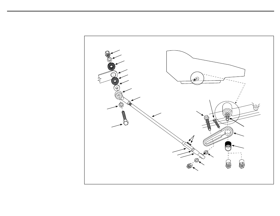
Install a small flat washer onto the 5/16"-24 x 1-1/2"
bolt. Then slide the bolt through the 5/16"-24 female rod
end. Next install the large diameter flat washer onto the
bolt, and one Delrin® bushing facing the proper direc-
tion. Insert the bolt through the steering column arm,
and then install the other Delrin® bushing and small flat
washer. Secure it all using the 5/16"-24 nylock nut as
shown in
Fig. 4.
NOTE: These items can be installed in the reverse order if
necessary for clearance or proper alignment.
Step 5: Thread the stainless steel rod into the rod end on the
steering column arm, leaving about 1/4" of threads
exposed beyond the jam nut.
Step 6: Check to make sure that nothing will interfere with con-
necting the stainless steel rod to the adjustable trans arm.
If required, the stainless steel rod can be bent to clear
other components, starting at the steering column end.
Step 7: Line up the transmission end of the stainless steel rod
with the center of the slot in the trans arm, and mark
the stainless steel rod at the center of the trans arm slot.
Measure 1-3/4" back towards the column end from your
mark, and cut the stainless steel rod at that point using a
metal cutting saw or cutoff wheel.
Step 8: Slide the hex connector with the second 5/16"-24 female
rod end onto the end of the stainless steel rod. Attach
the rod end to the adjustable trans arm with the 5/16"-
24 X 1-1/4" hex head bolt, two flat washers, and nylock
nut as shown in
Fig. 4. Tighten the set screws in the hex
connector using a 1/8" hex wrench, but only enough to
mark the stainless steel rod and hold the hex connector
in place during the adjustment procedure.
Step 9: Adjust the column shift linkage so that the shift lever will
enable you to get the transmission into all gear ranges.
Once you have the final adjustment done, tighten the jam
nuts at both ends of the stainless steel rod. Tighten the
1/4"-20 x 7/8" socket head bolt on the adjustable trans
arm to clamp it to the trans arm bushing.
Step 10: Disconnect the stainless steel rod from the hex connec-
tor and grind two small flat spots on the rod where each
of the set screws contact it (this will help maintain the
position of the rod). Apply thread locking compound
(not supplied) to the set screws, and then install and
tighten them.
Note: Also included in this kit are two standoff bolts, a 10mm
(has nicks on hex) and a 3/8"-16. These bolts are only
used with the Lokar Part No. BL-1400U, Back-Up Light or
Neutral Safety Switch Kit. These are to retain the back-up
light or neutral safety switch trigger to the selector shaft.
INS0058 Rev. 03/27/14
Page 2
© 2013 Lokar, Inc.
3
9
6
12
Steering Column Arm
(not included)
Delrin® Bushing
Delrin® Bushing
5/16" -24 x 1-1/2"
Hex Head Bolt
Small Flat
Washer
Large Flat Washer
Small Flat Washer
Jam Nut
Nylock Nut
5/16"-24 Female Rod End
5/16" x 21"
Stainless
Steel Rod
Set Screws
Transmission (not included)
Position Adjustable Trans Arm
at approximately 8:00
1/4"-20 x 7/8"
Socket Head Bolt
Transmission Selector
Shaft (not included)
Adjustable Trans Arm
with Lokar Logo facing
Transmission
Splined Trans
Arm Bushing
5/16" -24 x 1-1/4”
Hex Head Bolt
Flat Washer
Flat Washer
Nylock Nut
Hex Connector
5/16”-24 Female Rod End
3/8"-16
Trans Arm Nut
10mm
OR
Jam Nut
Fig. 4
Column Shift Linkage Installation Instructions for GM TH350, TH400, 700-R4, TH200, TH200-4R, 4L60, 4L60E, and 4L80E