Wiring - diagram c, Diagram c – Flex-a-Lite 65: Puller mode, does not include controls Chevy S-10 & S-10 Blazer Electric Fan User Manual
Page 2
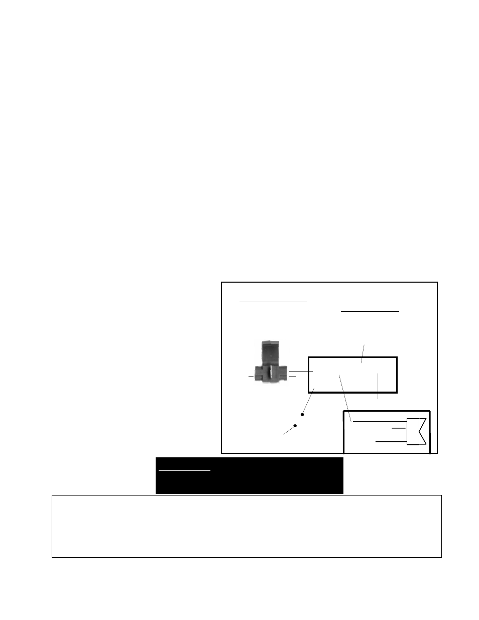
Wiring - Diagram C
Mandatory Connections
1. Connect the positive “+” terminal to a low amp 12 volt positive (+) source. (i.e. fuse box) using
thin red wire and fuse taps (if necessary) provided in the kit.
Note:
Attach this wire to an ignition controlled source to stop the fan unit from operating when
the vehicle is shut off.
2. Connect the “B” terminal to a high amp 12 volt positive (+) power source. (i.e. battery, starter
solenoid) using the thick red wire and in line fuse holder provided in the kit (do not install the
fuse at this time).
3 Connect the “G” terminal to ground. (i.e. chassis, negative(-) side of battery) using the thick
black wire provided in the kit.
5. If you have air conditioning: with 3-way connector provided, pass the A/C clutch positive(+)
wire (connected to the A/C compressor) through the connector. Place the green wire provided
into the closed end of the connector. Crimp metal plate. Snap plastic cover into place. Attach
green wire to the "C" terminal of the control box.
Air Conditioning Relay activates fan when A/C is turned on
6. Insert probe in radiator core near upper hose. Install rubber cap over end of probe.
.
Adjusting the Temeprature Control
1. Turn the adjustable control knob completely clockwise.
2. Idle the vehicle, when the vehicle is at 5 to 10 degrees higher than “normal” turn the adjustable
control knob counter clockwise until the fan comes on.
3. The fan will now activate at this temperature automatically and will shut off after it has cooled
the vehicle down 7 to 11 degrees. Note: It is typical for this fan unit to cycle on and off.
rev. 06-22-05 99925 page 2 of 2
*WARNING: If not using Flex-a-lite’s
illuminated switch (PN #31148), you must
disconnect the switch ground.
The Flex-a-lite Limited Warranty
Flex-a-lite Consolidated, 7213-45th St. Ct. E., Fife, WA 98424, Telephone No. 253-922-2700, warrants to the original purchasing user, that all Flex-a-lite products to be free of defects
in material and workmanship for a period of 365 days (1 year) from date of purchase. Flex-a-lite products failing within 365 days (1 year) from date of purchase may be returned to
the factory through the point of purchase, transportation charges prepaid. If, on inspection, cause of failure is determined to be defective material or workmanship and not by misuse,
accidental or improper installation, Flex-a-lite will replace the fan free of charge, transportation prepaid. Flex-a-lite will not be liable for incidental, progressive or consequential
damages. Some states do not allow the exclusion or limitaion of incidental or consequential damages, so the above limitation or exclusion may not apply to you. This warranty gives
you specific legal rights and you may have other rights, which vary from state to state. The Flex-a-lite warranty is in compliance with the Magnuson-Moss Warranty Act of 1975.
Diagram C
Optional Connection—
*Illuminated Manual Switch
(Note: Based on Flex-a-lite’s manual switch
part # 31148, not included)
(this step is based on Flex-a-lite’s part #31148, other
swtches will cause this unit to fail)
1. Connect the “M” terminal to terminal 1
on the switch.
2. Connect terminal 2 to a 12 volt posi-
tive(+) source.
3. Attach terminal 3 to ground to illumi-
nate the switch.
B
C
M
G
+
Ground
12 Volt Positive Source
12 Volt Positive
Source
Control Box
Fuse Holder
Control Box Terminals & Connections
Mandatory Connections
+ 12 volt positive source
G Ground
B 12 volt positive source
C Air conditioning relay
Optional Connection
M
Manual switch
12 Volt Source
12
3
Ground
(Illuminate switch)
A/C positive (+)
wire from clutch
3-way
connector
optional