Diagram b – Flex-a-Lite 165 Black Magic for the TOYOTA 4 x 4 (1984-19964&6 cyl.) User Manual
Page 2
MANDATORY CONNECTIONS
1. Disconnect the battery negative terminal.
2. Connect the “+” terminal of the control box to a 12V positive (+) power source (i.e. fuse box), using the thin red wire
and fuse taps (if necessary) provided in the kit.
Note: Attach this wire to an ignition controlled source to stop the fan when the vehicle is shut off.
Note: Attach this wire to a non-ignition source to keep the fan running after the vehicle is shut off.
3. Connect the “B” terminal to a high amp 12V positive power source (i.e. battery, alternator) using the thick red wire
and in line fuse holder provided in the kit. (Do not install fuse at this time)
4. Connect the “G” terminal to ground (i.e. chassis, negative side of battery) using the thick black wire provided in the
kit.
5. If you have air conditioning: with 3-way connector provided, pass the A/C clutch positive(+) wire (connected to
the A/C compressor) through the connector. Place the thick green wire provided into the closed end of the connector.
Crimp metal plate. Snap plastic cover into place. Attach green wire to the "C" terminal of the
control box. Air Conditioning Relay activates fan when A/C is turned on
6. Insert probe in radiator core near upper hose. Install rubber cap over end of probe
ADJUSTING THE TEMPERATURE CONTROL
1. Attach the temperature control knob to the control box.
2. Turn the knob clockwise completely.
3. Idle the vehicle, observe the temperature of the vehicle.
(Use the vehicles gauge)
4. When the temperature of the vehicle reaches above
normal, turn the control knob counter-clockwise
until the fan turns on. From here on the fan should
activate at this temperature setting. Adjust as
necessary according to your vehicle needs.
OPTIONAL CONNECTIONS
Manual Switch (not included) - Allows
manual operation of the fan.
(This step is based on Flex-a-lite’s manual switch part
#31148, other switches will cause this unit to fail)
1. Connect the “M” terminal to terminal 1 on the switch.
2. Attach terminal 2 of the switch to a 12V positive (+)
source.
3. Attach terminal 3 of the switch to ground, in order to
illuminate the switch.
Note (optional): To stop the fan from activating
thermostatically, omit the lead to the “+” terminal of
the control box. “B”, “G”, & “M” must remain
connected.
*WARNING: If not using Flex-a-lite's
illuminated switch (PN #31148) you must
disconnect the switch ground.
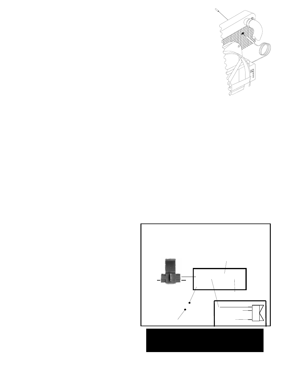
POSITION CAPILLARY TUBE
(See DIAGRAM B)
This temperature sensor sends engine coolant data to the temperature control for more effi-
cient cooling of your vehicle. The temperature sensor needs to be carefully placed through the
radiator core to detect engine coolant temperature.
1. Locate your radiator inlet hose; one of two large hoses that attach to the radiator. The inlet
hose from the engine should be mounted higher than the other hose. Release the clip holding
the thin capillary tube. Mount the fan so you can reach the inlet hose with the temperature
probe. Be careful not to kink or pinch the capillary tube.
2. With a small Phillips style screwdriver, gently separate the cooling fins on the radiator near
the inlet hose. You will gently push the screwdriver through the radiator to create a hole for
the temperature sensor to rest. Move only the thin fins, do not disturb the thicker tubes
which carry the coolant through the radiator.
3. Remove the protective cap and gently push the temperature sensor through the hole. The
temperature sensor should fit snug in the core.
4. After placing the sensor, replace the plastic cap. It is important to replace the cap to prevent
the tube from pulling out of the radiator. The cap also insulates the sensor from cool air passing
through the grill.
5. Gently coil the extra capillary tube and place it out the way of moving
objects. Be careful no to kink the tube. If you must put a bend in the tube,
bend the tube around a pen or small bolt to prevent pinching the tube.
Diagram B
B
C
M
G
+
Ground
12 Volt Positive Source
12 Volt Positive Source
Control Box
Fuse Holder
Control Box Terminals & Connections
Mandatory Connections
+ 12 volt positive source
G Ground
B 12 volt positive source
C Air conditioning relay
Optional Connection
M
Manual switch
12 Volt Source
12
3
Ground
(Illuminate switch)
A/C
positive
(+)
wire
from
clutch
3-way
connector
optional
Rev. 10-19-09
part no. 99971
Page 2 of 2