Flex-a-Lite 328: puller with out controls LoBoy Fan & Aluminum Shroud for Ford Coup 1930-34 User Manual
Page 3
Rev. 07-13-10 99318 Page 3 of 3
Step 9: (Optional) For manual switch operation, use Flex-a-lite p/n 31148. Connect the switch as shown
on the wiring diagram (previous page). Connect the "M" terminal on the control module to the "1" terminal
on the switch. Connect the "2" terminal on the switch to a positive 12v power source. Connect terminal "3"
on the switch to a good ground (for switch illumination).
NOTE: To prevent thermostatic activation (if
only manual switch operation is desired), omit the lead to the "+" terminal of the control box. "B",
"G", "M+" and "M-" must remain connected. If not using a Flex-a-lite manual switch, do not con-
nect a ground wire to the switch!
Step 10: Use the zip ties provided to secure the wires and prevent them from interfering with fan blades,
belts, and pulleys in the engine compartment. Reconnect the battery and insert the fuse provided.
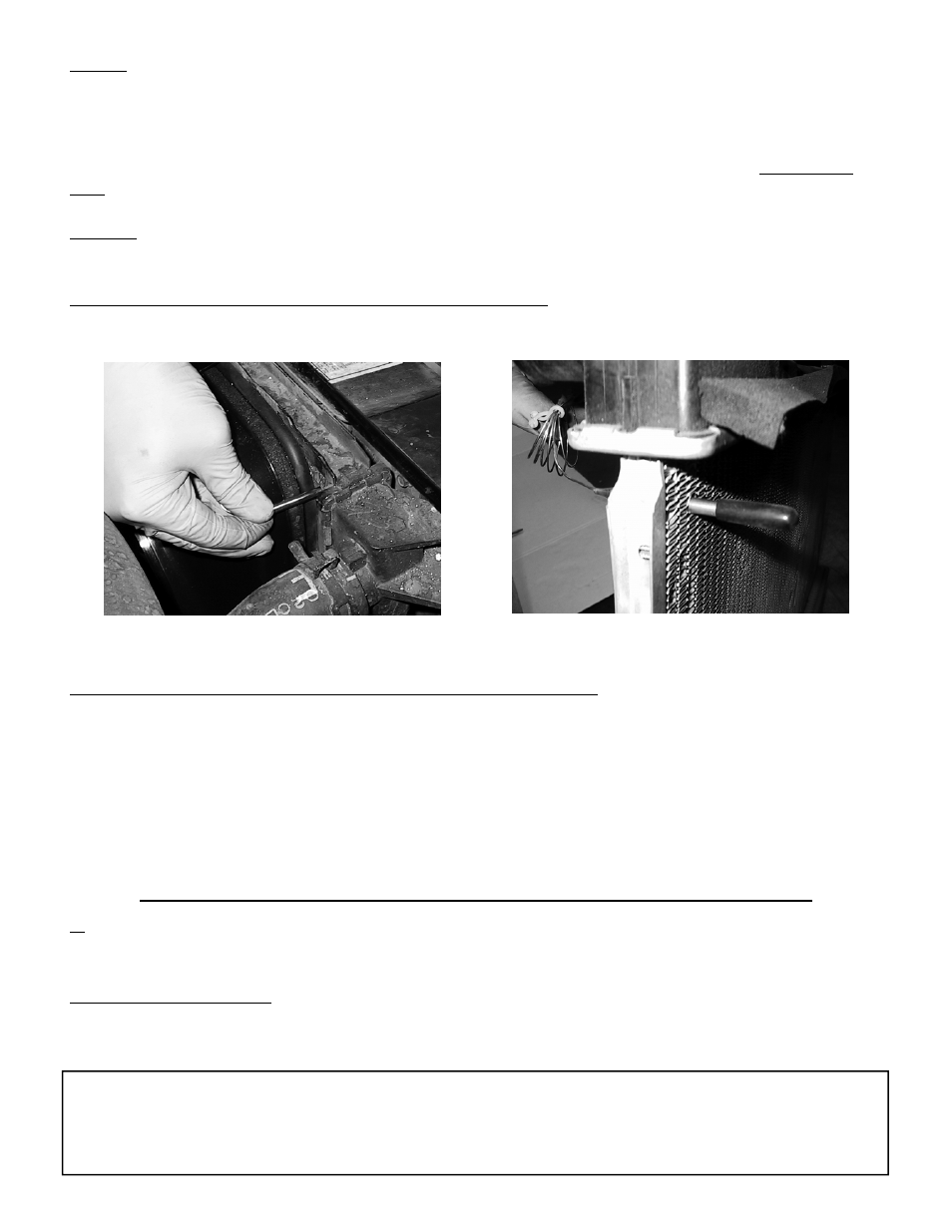
Step 11: Insert the temperature probe into the radiator fins
Install temp. probe near inlet hose...
then replace the insulator cap.
Locate the inlet hose from the engine to the radiator. Remove the black insulator cap and insert the temp.
probe through the radiator fins near the inlet hose. Reinstall the black insulator cap.
Step 12: Adjust the temperature control knob on the control box
If you disconnected any hoses or drained coolant to install the fan, reconnect the hoses and refill the
radiator. Turn the knob clockwise until it stops. Start the engine and allow it to idle. Using a digital ther-
mometer (positioned near the inlet hose) or the vehicle's temperature guage, monitor the temperature.
When the coolant temp. is slightly above normal (or desired temp.), turn the knob counter-clockwise just
until the fan turns on. From now on, the fan should activate at this temperature setting. Adjust as neces-
sary to maintain desired temperature.
The Flex-a-lite Limited Warranty
Flex-a-lite Consolidated, 7213-45th St. Ct. E. Fife, WA 98424, Telephone No. 253-922-2700, warrants to the original purchasing user, that all Flex-a-lite products to be free of defects in material
and workmanship for a period of 365 days (1 year) from date of purchase. Flex-a-lite products failing within 365 days (1 year) from date of purchase may be returned to the factory through the
point of purchase, transportation charges prepaid. If, on inspection, cause of failure is determined to be defective material or workmanship and not by misuse, accidental or improper installation,
Flex-a-lite will replace the fan free of charge, transportation prepaid. Flex-a-lite will not be liable for incidental, progressive or consequential damages. Some states do not allow the
exclusion or limitation of incidental or consequential damages, so the above limitation or exclusion may not apply to you. This warranty gives you specific legal rights and you may have other
rights, which vary from state to state.
The Flex-a-lite warranty is in compliance with the Magnuson-Moss Warranty Act of 1975.
Fan Wiring Instructions; #328 with out controls only
1. Wire the fan motor to power source (control unit or switch and relay if desired). Connect the
red wire from
the fan motor to a 12v. positive (+) source. Connect the
black motor wire to a ground (-) source.
NOTE: Failure to do this will result in incorrect operation and damage to the fan motor!
2. Connect a fuse holder. Be sure to connect a fuse holder in-line with the positive (+) power wire to
protect the fan motor and your vehicle’s electrical system from damage.