Fan wiring instructions; #318 with controls only, Wiring diagram - model #318 – Flex-a-Lite 328: puller with out controls LoBoy Fan & Aluminum Shroud for Ford Coup 1930-34 User Manual
Page 2
Fan Wiring Instructions; #318 with controls only
Step 2: Locate mounting point for control
Locate a mounting point for control near inlet side of radiator. Control needs to be placed within 18" of
radiator inlet hose. You may want to mount next to radiator on fender well. Mount control using screws
provided.
Step 1: Mount radiator/fan
Follow radiator mounting instructions- found on previous page.
Step 3: Wire the fan motor (refer to Wiring Diagram, below)
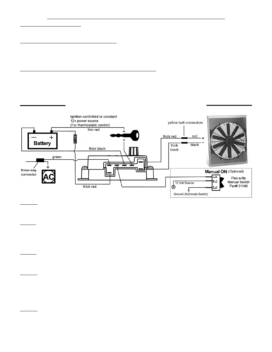
Using the yellow butt connectors provided, attach a length of the large diameter (12 AWG)
red wire to the
red motor wire at fan. Attach a length of the large diameter (12 AWG) black wire to the black motor wire at
the fan. Once the fan is in place, these will attach to the control module. If mounting the control some-
where in the engine compartment, leave enough wire to reach the control module, but do not connect yet.
Step 5: Disconnect the negative battery lead for safety while finishing the wiring. Use the large diameter
red (12 AWG) wire to run power directly from the battery positive (+) terminal to the "B" terminal on the
control module. Connect the fuse holder in-line with this wire, as shown, but do not insert the fuse yet. Use
the blue female, ring, and butt connectors provided.
Step 6: Use the large diameter black (12 AWG) wire to run from the negative (-) battery terminal to the "G"
terminal on the control module. Use the blue female connector and ring connector provided.
Step 7: Use the small diameter red wire (18 AWG) to connect the "+" terminal on the control module to a
positive power source.
NOTE: Attaching this wire to an ignition-controlled source will shut off the
fan when the engine is turned off. Attach this wire to an uninterrupted (always hot) power source to
allow the fan to continue running after the engine is shut off. Use the blue female connector and fuse
taps (included) if necessary.
Rev. 07-13-10 99318 Page 2 of 3
WIRING DIAGRAM - MODEL #318
Step 8: (Optional) For air conditioning control (if desired) connect the "C" terminal on the control module to
the
positive wire that triggers the A/C compressor using the small diameter green (14 AWG) wire. Using a
voltmeter, determine which wire coming from the compressor is the
positive trigger wire. Use the blue "tap-
in connector" (included) to tap into this wire and send a signal to the fan control module. The fan will cycle
on and off with the A/C clutch when the A/C is turned on.
Step 4: Connect the motor wires to the control module
(Red wire to the "M+" terminal and black wire to the "M-" terminal).