Fan wiring instructions – Flex-a-Lite 56484 Camaro Radiator and Fan Combo Fits 1982-1992 User Manual
Page 4
Fan Wiring Instructions
FOLLOW THESE INSTRUCTIONS CAREFULLY TO AVOID DAMAGING THE CONTROL UNIT,
FAN MOTORS, AND YOUR VEHICLE! WHEN CRIMPING WIRES, ALWAYS USE A QUALITY
CRIMPING TOOL (DO NOT USE PLIERS OR OTHER DEVICES).
Step 1: Locate mounting point for the VSC (variable speed control) unit
Locate a mounting point for the VSC near inlet side of the radiator. The control unit needs to be placed within
about 2-feet of radiator inlet hose. On the fender well next to the radiator may be a convenient location. At-
tach the control unit using the screws provided.
Step 2: Wire the fan motors (refer to Wiring Diagram, below)
Using the large yellow butt connectors provided, attach a length of the thick (10 AWG) red wire to the red motor
wires at fan. Attach a length of the thick (10 AWG) black wire to the black motor wires at the fan. Once the fan
is in place, these will attach to the control unit. If mounting the control somewhere in the engine compartment,
leave enough wire to reach the control unit.
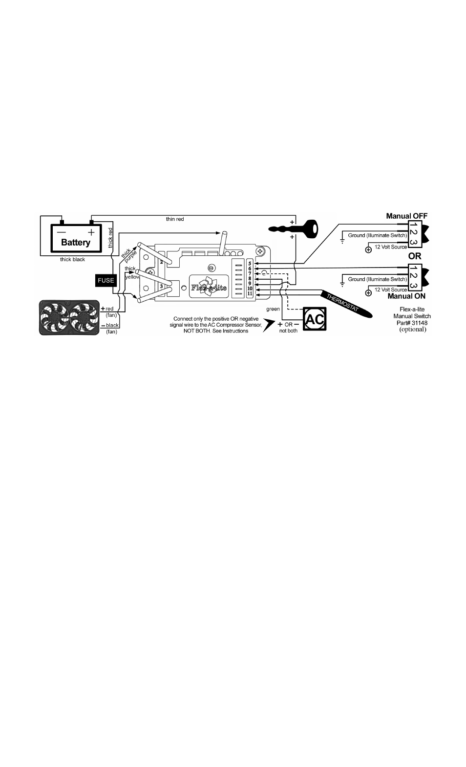
WIRING DIAGRAM
NOTE: For pusher configuration, flip the fan blades over and reverse motor wire polarity
(black motor wire positive, red wire negative).
3. Connect the fan wires to the VSC
Now begin wiring the motors to the VSC. Using the yellow butt connectors provided, connect the red wire you
attached to the fan motor wires in Step 2 to the yellow wire on the VSC. Connect the black wire from the
motor wires to the purple wire on the VSC. (see wiring diagram) NOTE: Failure to do this will result in
incorrect operation and damage to fan motors!
4. Connect power leads
Determine the length needed to run thick red and black wire from the VSC to the battery terminals and trim
appropriately. Crimp a large yellow ring connector to one end of the each wire and connect the black wire to
the negative (-) battery terminal, but Do Not connect the red wire yet. Using butt connectors, connect the fuse
holder provided inline with the red wire. The fuse and fuse holder will protect the fan motors and your vehicle’s
electrical system from damage.
5. Ignition controlled power source
Locate fuse box. Find a circuit that is “hot “ when the key is in the “ON” position. NOTE: DO NOT use the
DRL or brake/taillight fuse! Attach the included fuse tap to fuse. Attach a female connector to the thin red
wire included and connect to the fuse tap. Trim the wire so that it will reach the VSC. Attach pink female
connector to end of wire and connect to terminal #9 on VSC.
6. Fan operation with air conditioning
Locate the wires coming from the A/C compressor. Determine which wire is ground and which is positive by
using a volt meter. Connect or splice the thin green wire to the positive (+) wire of the A/C compressor using
the blue “Piggy-Back” connector. Determine length needed to reach VSC and trim to length. Attach a pink
female connector to the wire. If the A/C compressor is activated by a positive (+) signal, connect this wire to
terminal #8 on VSC. If it is activated by a negative signal, connect to terminal #7 on VSC.
7. Temperature sensor
Locate the temperature sensor. Gently push probe through fins in radiator as close to the upper radiator hose
as possible, leaving about ¼” of the probe protruding out of the core. Place small black cap over exposed end
of probe seen through fins. Determine the length of wire needed to reach the VSC. IMPORTANT: Strip the
insulation back about 1" and fold the wire onto itself to effectively double the thickness of the wire before
connecting the pink female connectors as shown in at right. Attach these wires to terminals #10 & 11 on the
VSC. Both wires need to be connected but it doesn’t matter which wire goes to each terminal.
Rev. 09-14-09
#99484 Page 4 of 5