Boonton 4240 series rf power meter, Getting started 3-7 – Boonton 4240 RF Power Meter User Manual
Page 31
Boonton 4240 Series RF Power Meter
DUAL CHANNEL
A
C
M M M M M L
U
P
K
∆
± D D D D D D U U U
(
B A R G R A P H )
A
C
M M M M M L ± D D D D D D U U U U
P
K
∆
(
B A R G R A P H )
SINGLE CHANNEL
A
C
M M M M M L ± D D D D D D U U U U
P
K
∆
(
B A R G R A P H )
KEY:
D
"
=
"
0 through 9 or a decimal point
M M
"
=
"
CH1, CH2, CH1+2, CH1/2
U U U
"
=
"
V, mV, nW, uW, mW, kW, MW,dBm,
L
"
=
"
∧
,
∨
(alarm
mode)
M M M
U
dBnW,
dBuW,
dBnV,
dBuV,
dBmV,
dBV
A
C
"
=
"
Active Channel pointer
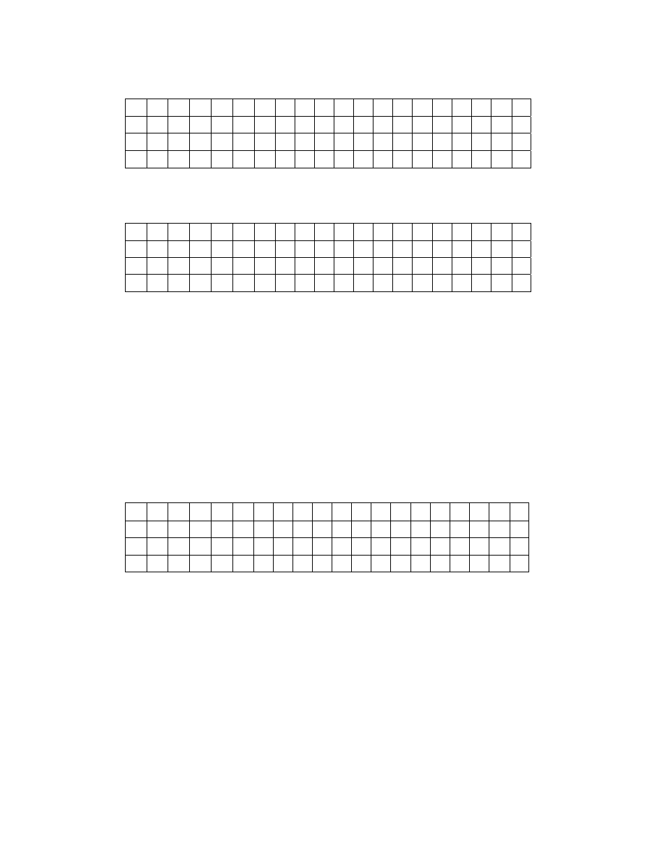
Figure 3-3. Measurement Display, Local Mode
A
C
M M M M M L ± D D D D D D U U U U
P
K
∆
(
B A R G R A P H )
A
C
M M M M M L ± D D D D D D U U U U
P
K
∆
R E M
L S N
T L K
S R Q
KEY:
REM
"
=
"
Remote mode enabled
LSN
"
=
"
Listener addressed
TLK
"
Talker
dressed
Service Reque t activated
Figure 3-4. M
u
t D p y,
em te Mode
ad
"
=
SRQ
"
=
"
s
eas remen
is la R
o
Getting Started
3-7