2 diode detection, 2 diode detection -3, Boonton 4240 series rf power meter – Boonton 4240 RF Power Meter User Manual
Page 111
Boonton 4240 Series RF Power Meter
6.1.2 Diode Detection
Wideband diode detectors are the dominant power sensing device used to measure pulsed RF signals. However, several diode
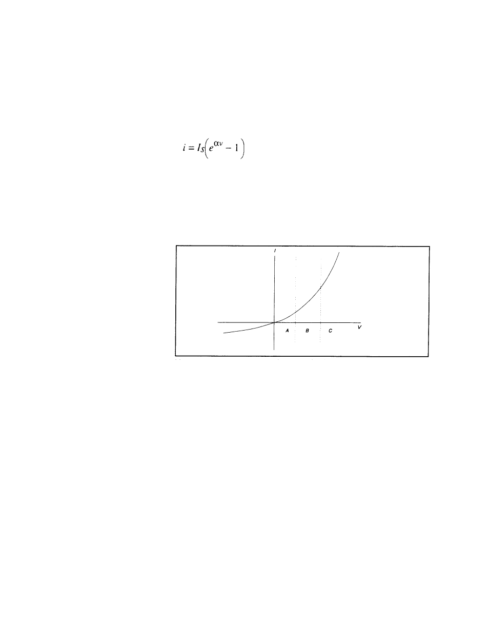
Detector Response. The response of a single-diode detector to a sinusoidal input is given by the diode equation:
v = net voltage across the diode
ed in F
The curv
r output is proportional to the
square o
gnal level
e output is
proportional to the input. In between
these ran
tor response lies bet
aw and linea
For accu
over all three regio
sponse is pre-calibrated over
the entir
on data is stored in t
and recalled to adjust each sample of the pulse power
measure
characteristics must be compensated to make meaningful measurements. These include the detector’s nonlinear amplitude
response, temperature sensitivity, and frequency response characteristic. Additional potential error sources include detector
mismatch, signal harmonics and noise.
where:
i = diode current
Is
= saturation current
α = constant
An ideal diode response curve is plott
igure 6-3.
Figure 6-3.
Ideal Diode Response
e indicates that for low microwav
vels (Regio
the sing -diode
f the input power. For high input si
s (Region C
linearly
e input le
n A),
le
detecto
), th
ges (Region B), the detec
ween square-l
r.
rate power measurements
ns illustrated in Figure 6-3, the detector re
e range. The calibrati
he instrument
ment.
Application Notes
6-3