Boonton 4240 series rf power meter, Getting started 3-2 – Boonton 4240 RF Power Meter User Manual
Page 26
Boonton 4240 Series RF Power Meter
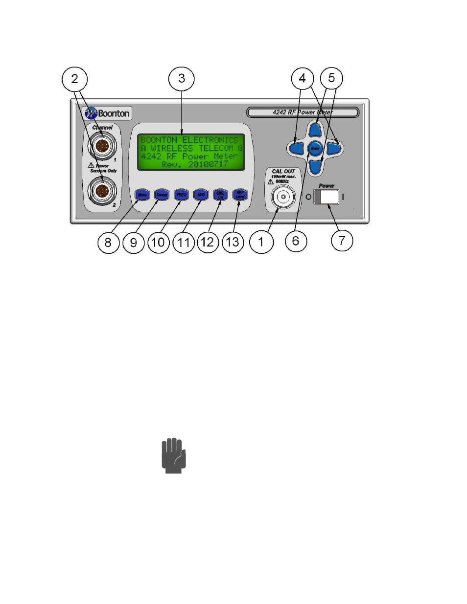
Figure 3-1. Standard 4240 Series RF Power Meter - Front Panel
Table 3-1 Operating Controls, Indicators and Connections
Reference #
Front Rear Nomenclature
Function
1
1
Internal Calibrator
The output of the built-in 50MHz programmable calibrator is available from a
Type-N connector located on the front, or optionally on the rear panel of the
instrument. This calibrator is used to automatically calibrate sensor offset and
linearity, and can also be used as a general purpose calibration signal source.
2
2
Channel Inputs
One or two Channel inputs are located on the front, or optionally on the rear
panel of the instrument. These are 10-pin precision connectors designed to accept
only Boonton CW power sensors.
Caution
Do not attempt to connect anything other than a
Boonton power sensor and sensor data adapter to the Channel inputs!
The Channel inputs are not measurement terminals and cannot be used
for other than the intended purpose.
3 Display
Screen
LCD
readout
of the measurements and user interface for editing of the
instrument's operating parameters.
Getting Started
3-2