BMR Suspension SP029 User Manual
Page 2
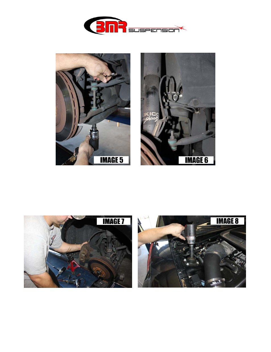
SP027 CONTINUED
10.
Using a 15mm wrench and socket, remove the sway bar end links. (IMAGE 5)
11.
Remove the brake lines from their clips as shown in IMAGE 6.
12.
Using a 15mm socket, remove the caliper bolts. Hang the caliper out of the way using a clothes hanger
or wire. (IMAGE 7)
13.
Remove the brake rotor to provide access to the lower A-arm.
14.
Place a jack under the lower A-arm.
15.
Using 21mm socket, loosen the upper strut nut then lower the A-arm far enough to remove the spring.
(IMAGE 8)
16.
Using a pry-bar, carefully pop the spring out of it’s seat. (IMAGE 9 on following page)
17.
Swap the isolator bushings from the OE springs to the BMR springs. (IMAGE 10 on following page)
18.
Install the BMR springs and lift the lower A-arm while guiding the strut through the strut tower. Once
the stud protrudes through the tower, thread the nut onto it and tighten to
19.
Re-install the brake rotor and caliper. Tighten the caliper bolts to
20.
Re-connect the brake lines to the clips on the spindle and frame.
CONTINUED