BMR Suspension TAS004 User Manual
Page 6
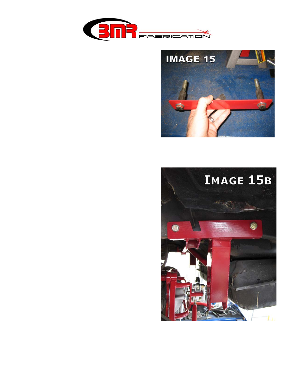
29. Assemble the outer reinforcement plate,
frame inserts, ½” bolts and stainless washers
as shown in Image 15. There are 2 different
length frame spacers. The ½” x 3.25” bolt
and 1.85” spacer goes in the rear hole while
the ½” x 3.5” bolt and 2.2” spacer goes in
the front hole. Slide the assembly through
the subframe until the bolts protrude through
the BMR cross-member on the inside of the
frame rail. Thread a nut and stainless
washer onto the exposed portion of the bolts
and then tighten these bolts to 80 ft/lbs.
30. Proceed to the driver’s side. The driver’s
side frame rail has a frame reinforcement
that makes it differ from the passenger side.
This requires a different reinforcement plate.
Position the plate as shown in Image 15b
and duplicate steps 24-29 using the
remaining spacers and same length bolts.
(CONTINUED)
6
- AA016 (2 pages)
- AA017 (1 page)
- AA018 (3 pages)
- AA028 (1 page)
- AA005 (3 pages)
- BCA005 (1 page)
- BK043 (2 pages)
- CCK002 (3 pages)
- RB001 (2 pages)
- RSK001 (1 page)
- RSK007 (2 pages)
- SB035 (3 pages)
- BCA003 (1 page)
- XSB006 (1 page)
- DSL002 (2 pages)
- TCA007 (1 page)
- AWK-1 (1 page)
- PSB001 (1 page)
- TCA018 (1 page)
- BCK003 (4 pages)
- BK046 (4 pages)
- BK006 (1 page)
- BK008 (1 page)
- BK016 (3 pages)
- BK017 (4 pages)
- BK018 (2 pages)
- BK019 (1 page)
- BK024 (4 pages)
- BK026 (4 pages)
- BK027 (5 pages)
- BK029 (4 pages)
- BK039 (4 pages)
- BK040 (3 pages)
- CCK004 (2 pages)
- DSL014 (2 pages)
- DSL015 (1 page)
- DTB004 (1 page)
- ELK004 (1 page)
- ELK005 (1 page)
- ELK006 (1 page)
- ELK009 (1 page)
- ELK011 (1 page)
- MM004 (2 pages)
- MTCA030 (2 pages)
- S5003 (4 pages)