BMR Suspension TAS004 User Manual
Page 3
3
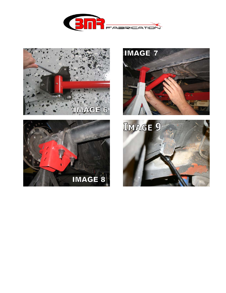
17. Install the BMR control arm mounts onto the axle using the supplied U-bolts. The open
portion of the mount should face forward as shown in Image 8. Tighten nuts to 90 ft/lbs.
18. Lift and insert the other end of the control arm into the axle brackets on the highest
mounting hole and insert the supplied ½” x 3.25” bolts. This connection should be left
loose until a later step. NOTE: it may be necessary to adjust the length of the control
arms to match the holes in the control arm mounts. It may also be necessary to move the
rear end forward or back to line the mounting holes up. If one trailing arm is adjusted,
duplicate this procedure on the other arm and verify that they are equal in length before
proceeding to the next step.
19. The next few steps involve installation of the shock cross-member. Begin by removing
the factory muffler hangers located above the rear end. (Image 9).
20. The cross-member can be welded or bolted into place. Locating the shock cross-member
properly is important and, while it can be performed by one person, it is much easier with
a helper. Have a helper hold the shock cross-member up into place on the frame rails.
Slide the cross-member as far forward as it will allow.
(CONTINUED)