Www.bmrfabrication.com – BMR Suspension KM008-1 User Manual
Page 3
TUBULAR K-MEMBER AND A-ARM INSTALLATION INSTRUCTIONS
(CONT.)
A-ARM INSTALLATION FOR COIL-OVER SPRINGS:
1. Lube the polyurethane bushings using the appropriate grease and install both A-arms into the K-
member. Insert the provided mounting bolts and nuts but do not tighten.
2. Using a 13/16” socket, remove the main nut that holds the strut into the upper strut bushing.
Remove the entire strut and brake assembly.
3. Using a marker or scribe, mark the upper strut mounts in relation to the strut tower. This will
make it easier to get the alignment close when re-assembling the car. Using a 13mm socket,
remove the 3 nuts retaining the mount to the strut tower.
4. Position the BMR upper spring mount under the strut mount, re-insert the 3 bolt flange and re-
install the nuts. Do not tighten at this time.
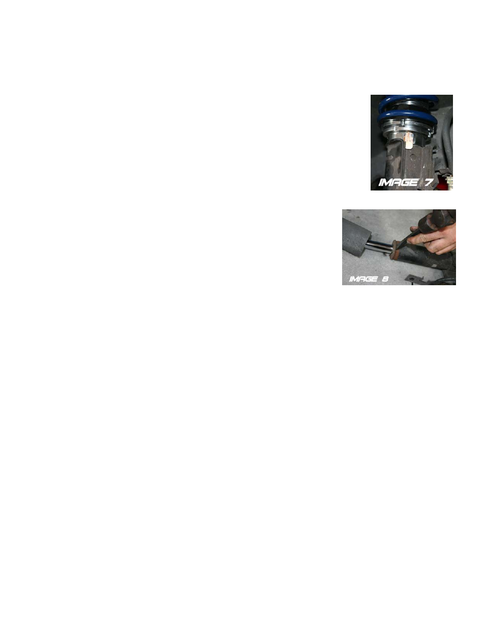
5. Slide the BMR spring collar over the strut with the protruding tab facing downward. This tab
should be positioned inside the strut mounting flange (See Image 7) and is necessary to prevent
the collar from turning. NOTE: Some struts have a ring attached to the top of the strut that prevents the BMR spring collar
from fitting. In this case, it is necessary to replace the strut with a different unit or
remove the ring with a hammer and chisel (See Image 8).
6. With the collar is positioned on the strut, slide the BMR lower spring seat over the
collar as in Image 7. Install one set of needle bearings on the spring seat then slide the
spring over the collar.
7. Lift the entire assembly up until the strut shaft protrudes through the upper strut
bushing and the spring seats on the upper spring seat. Install the main nut to hold the
strut in place. Do not tighten yet.
8. Lift the A-arm up until the ball joint seats into the spindle. Install the castle nut and
tighten. Insert a new cotter pin.
9. Repeat steps 3-8 for the other side.
10. Re-install the tie rod ends onto the spindles, tighten, and install new cotter pins.
11. Re-install the sway bar end links.
12. Remove the brake lines from the original K-member. With some slight adjustment to the brake lines, they are compatible
with the BMR K-member. Re-install the lines, mimicking their position on the stock K-member. Use the supplied zip-ties to
hold the brake lines in place. See Image 6 on page 2 for brake line routing.
13. Tighten all fittings and bleed the system.
14. Using the supplied spanner wrench, adjust the lower spring seat to approximately the middle of the adjuster. Tighten the jam
nut against the collar.
15. Re-install both front tires and lower the car.
16. Tighten the A-arm bolts with the car lowered. Grease all fittings in the A-arms until grease protrudes from the bushings.
17. Grease both lower ball joints until grease protrudes from the dust boot.
18. Bounce the car a few times to allow the suspension to settle. If the car is too high or too low, remove tires and adjust the
spring height accordingly.
19. Double-check all bolts for tightness. Double check all brake lines for clearance.
20. Connect battery and have suspension aligned.
WWW.BMRFABRICATION.COM
This product is an aftermarket accessory and not designed by the vehicles manufacturer for use on this vehicle. As such, buyer
assumes all risk of any damage caused to the vehicle/person during installation or use of this product.
Page 3