BMR Suspension KM008-1 User Manual
Page 2
TUBULAR K-MEMBER AND A-ARM INSTALLATION INSTRUCTIONS
(CONT.)
16. If installing traditional springs, please proceed to step 17 below. If installing the BMR coil-
over setup or equivalent, it is necessary to use the 4 provided aluminum shim washers when
installing the K-member. Position one washer under each of the front 4 main K-member bolts
and install the K-member. Use the factory bolts in all locations except the middle, use the
provided bolt in this location. Install all bolts but do not tighten. Proceed to step 19.
17. When installing traditional springs, it is necessary to also use BMR upper spring mounts (Part
#USP001). These mounts are particular to each side of the car and install in between the K-
member and the frame, essentially “sandwiching” the mount.
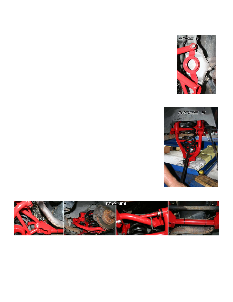
18. Position the mounts on top of the K-member in such a way that the spring seats angle outward.
Install the K-member (See Image 4). Use the factory bolts in all locations except the middle,
use the provided bolt in this location. Install all bolts but do not tighten.
19. Line up the motor mount holes and insert the cross-bolts. It may be necessary to lift or lower
the motor in order to line up the mounting holes. Tighten both cross-bolts. Tighten all 6 K-
member bolts and torque to 130 ft/lbs.
A-ARM INSTALLATION FOR TRADITIONAL SPRINGS:
1. Lube the polyurethane bushings using the appropriate grease and install both A-
arms into the K-member. The sway bar mounts should point towards the front of
the car. Insert the provided mounting bolts and nuts but do not tighten.
2. Swing the A-arm up and position a hydraulic jack underneath the A-arm. Lift the
spring up and position it onto the upper spring pocket, allowing the bottom of the
spring to rest on the A-arm pocket. Using a long pry-bar, pry the spring until it
pops into position in the spring pocket. NOTE: It may be necessary to lift the A-
arm in order to get the spring pocket at the correct angle for the spring to pop into
place. With the spring in position, the end of the spring should butt up against the
stop in the spring cup.
3. Once the spring is seated properly in the cup, carefully lift the A-arm until the ball
joint seats into the spindle. Install the castle nut and tighten. Insert a new cotter
pin.
4. Repeat steps 1-3 for the other side.
5. Re-install the tie rod ends onto the spindles, tighten, and install new cotter pins.
6. Re-install the sway bar end links.
7. Remove the brake lines from the original K-member. With some slight
adjustment to the brake lines, they are compatible with the BMR K-member. Re-
install the lines, mimicking their position on the stock K-member. Use the supplied zip-ties to hold the brake lines in
place. See Image 6 below for brake line routing.
8. Tighten all fittings and bleed the system.
9. Re-install both front tires and lower the car.
10. Tighten the A-arm bolts with the car lowered. Grease all fittings in the A-arms until grease protrudes from the bushings.
11. Grease both lower ball joints until grease protrudes from the dust boot.
12. Double-check all bolts for tightness. Double check all brake lines for clearance.
13. Connect battery and have suspension aligned.
PAGE 2