Rear panel leds, Controller enclosure-rear panel layout, Controller enclosure—rear panel layout – HP MSA 1040 SAN Storage User Manual
Page 70: 28 msa 1040 array: rear panel
70
LED descriptions
Rear panel LEDs
Controller enclosure—rear panel layout
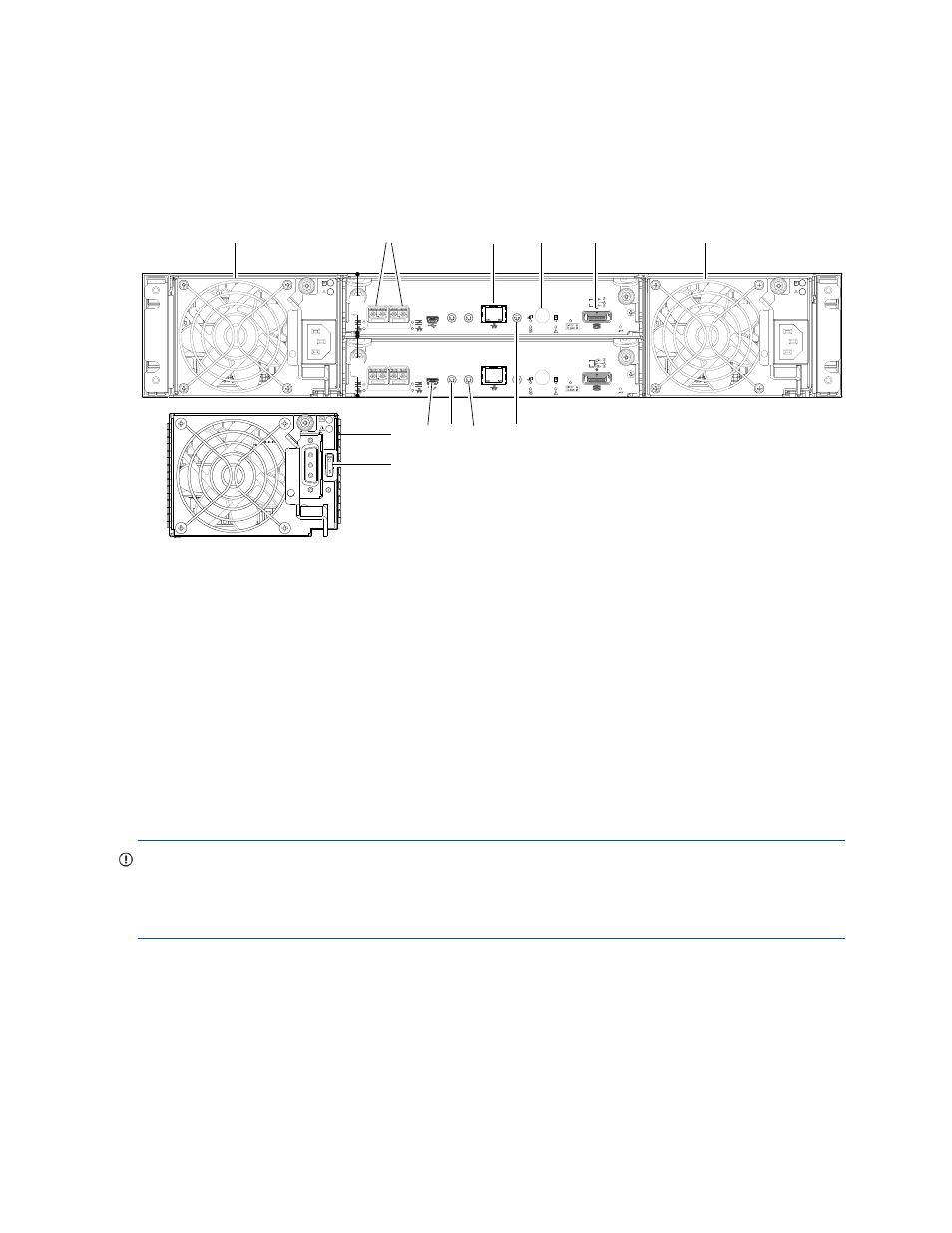
The diagram and table below display and identify important component items comprising the rear panel
layout of the MSA 1040 controller enclosure. Diagrams and tables on the following pages further describe
rear panel LED behavior for component field-replaceable units.
Figure 28 MSA 1040 Array: rear panel
A controller enclosure accommodates two power supply FRUs of the same type—either both AC or both
DC—within the two power supply slots (see two instances of callout 1 above). The controller enclosure
accommodates two controller module FRUs of the same type within the I/O module slots (see callouts 2
and 3 above).
IMPORTANT:
If the MSA 1040 controller enclosure is configured with a single controller module, the
controller module must be installed in the upper slot (see callout 2 above), and an I/O module blank must
be installed in the lower slot (see callout 3 above). This configuration is required to allow sufficient air flow
through the enclosure during operation.
The diagrams with tables that immediately follow provide descriptions of the different controller modules
and power supply modules that can be installed into the rear panel of an MSA 1040 controller enclosure.
The controller module for your product is pre-configured with the appropriate SFP for the selected host
interface protocol. Showing controller modules and power supply modules separately from the enclosure
provides improved clarity in identifying the component items called out in the diagrams and described in
the tables.
Descriptions are also provided for optional drive enclosures supported by MSA 1040 controller enclosures
for expanding storage capacity.
1
AC Power supplies [see
2
Controller module A [see
3
Controller module B [see
4
Host ports: used for host connection or replication
5
CLI port (USB - Type B)
6
Service port 2 (used by service personnel only)
7
Reserved for future use
8
Network port
9
Service port 1 (used by service personnel only)
10
Disabled button (used by engineering only)
(Stickers shown covering the openings)
11
SAS expansion port
12
DC Power supply (2) — (DC model only)
13
DC Power switch [see
CACHE
LINK
ACT
6Gb/s
CACHE
LINK
ACT
6Gb/s
CLI
CLI
SERVICE−1
SERVICE−2
CLI
CLI
SERVICE−1
SERVICE−2
PORT 1
PORT 2
PORT 1
PORT 2
1
4
8
q
1
=
6
9
w
-
5
7
2
3
MSA 1040 controller enclosure
(rear panel locator illustration)