24 connecting a usb cable to the cli port – HP MSA 1040 SAN Storage User Manual
Page 38
38
Connecting to the controller CLI port
NOTE:
For more information, see Using the Configuration Wizard > Configuring network ports within the
HP MSA 1040 SMU Reference Guide.
Setting network port IP addresses using the CLI port and cable
You can set network port IP addresses manually using the command-line interface port and cable. If you
have not done so already, you need to enable your system for using the command-line interface port [also
"Using the CLI port and cable—known issues on Windows" (page 40)
NOTE:
"Preparing a Linux computer before cabling to the CLI port" (page 37)
. For
Windows systems see
"Downloading a device driver for Windows computers" (page 37)
Network ports on controller module A and controller module B are configured with the following
factory-default IP settings:
•
Management Port IP Address: 10.0.0.2 (controller A), 10.0.0.3 (controller B)
•
IP Subnet Mask: 255.255.255.0
•
Gateway IP Address: 10.0.0.1
If the default IP addresses are not compatible with your network, you must set an IP address for each
network port using the command-line interface embedded in each controller module. The command-line
interface enables you to access the system using the USB (universal serial bus) communication interface
and terminal emulation software. The USB cable and CLI port support USB version 2.0.
Use the CLI commands described in the steps below to set the IP address for the network port on each
controller module. Once new IP addresses are set, you can change them as needed using the SMU. Be
sure to change the IP address via the SMU before changing the network configuration.
NOTE:
Changing IP settings can cause management hosts to lose access to the storage system.
1.
From your network administrator, obtain an IP address, subnet mask, and gateway address for
controller A, and another for controller B.
Record these IP addresses so that you can specify them whenever you manage the controllers using the
SMU or the CLI.
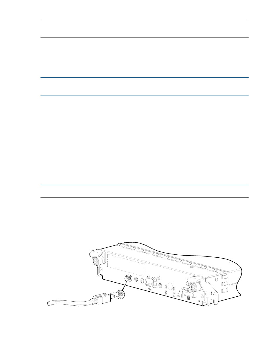
2.
Use the provided USB cable to connect controller A to a USB port on a host computer. The USB mini 5
male connector plugs into the CLI port as shown in
(generic controller module is shown).
Figure 24 Connecting a USB cable to the CLI port
3.
Enable the CLI port for subsequent communication:
CACHE
LINK
DIRTY
LINK
ACT
CLI
CLI
Host Interface
Not Shown
SERVICE−2
SERVICE−1
6Gb/s
Connect USB cable to CLI
port on controller faceplate